
Optical storage medium enabling uniform light transmittance, optical read/write apparatus for same, and optical read/write method for same

a technology of optical storage media and light transmittance, applied in mechanical recording, record information storage, recording signal processing, etc., can solve the problems of inability to perform stable write/readout, add complexity to the write/read system, and difficult to achieve optical writing/reading system using such an optical disk

Inactive Publication Date: 2007-02-20
SHARP KK
View PDF16 Cites 41 Cited by
  • Summary
  • Abstract
  • Description
  • Claims
  • Application Information

AI Technical Summary

Benefits of technology

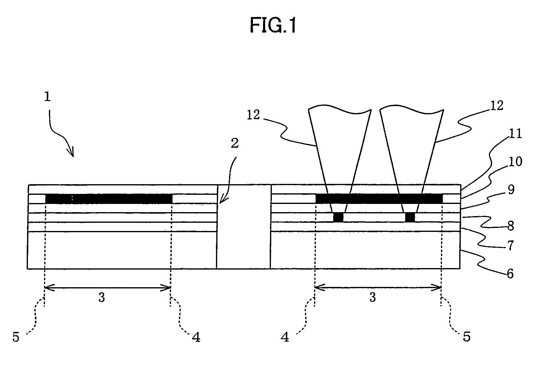
[0027]The present invention has an objective to offer an optical storage medium, an optical read / write apparatus, and an optical read / write method, with which light can be shone with uniform intensity across the substantially entire recordable area of the second data storage layer without using a complex read / write system even under such conditions that the transmittance to light of the first data storage layer in the recordable area may vary depending on whether any data is recorded in the recordable area.
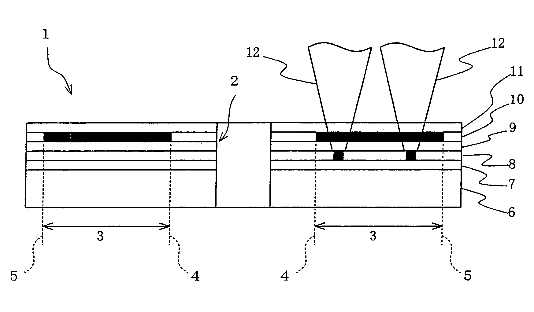
[0041]On the other hand, the present invention is arranged so that the address area in the first data storage layer of the optical storage medium includes a recorded area exhibiting a varied transmittance and a non-recorded area exhibiting an original transmittance. Thus, also in the address area, an optical transmittance is varied due to the recorded area as in the non-address area. Therefore, as described above, the intensity of the light beam reaching the second data storage layer after passing through the address area of the first data storage layer on the light-striking side can be made to be almost the same as the intensity of light beam reaching the second data storage layer after passing through the non-address area in the recordable area of the first data storage layer. As a result, it is possible to read / write data from / in the second data storage layer steadily and desirably.
[0042]According to the optical read / write apparatus or the optical read / write method, in a case where the recorded area is formed on the address area in the first data storage layer of the optical storage medium, it is possible to manufacture the optical storage medium at a lower cost since the manufacturing process of the optical storage medium is simplified.
[0043]Further, still another object of the present invention is to provide an optical storage medium, an optical read / write apparatus, and an optical read / write method, with which data can be read / written steadily without being influenced by a prepit area. This is realized in an optical disc having two or more storage layers.
[0048]According to the foregoing apparatus and method, an envelope of a reproduction signal obtained when the prepit area is reproduced is detected by the envelope detecting section. Then, the mean level producing section produces a mean level of the detected envelope. Thereafter, the digital converting section converts the reproduction signal to a digital signal using the mean level as a reference. Thus, the mean level is always detected, and the detected mean level is used as a reference in the digital conversion, so that it is possible to perform the digital conversion without being influenced by variance in amplitude of the reproduction signal. For example, in a case where there exist a fully recorded portion exhibiting high transmittance after recording and an unrecorded portion which holds no record, when a light beam that is projected so as to cover the fully recorded portion and the unrecorded portion is focused on the second storage layer, it is possible to steadily obtain a digital signal from the reproduction signal even though the reproduction signal strength of prepit data varies in connection with rotation of the optical storage medium. Thus, it is possible to-steadily reproduce the prepit data on the second storage layer of the optical storage medium.

Problems solved by technology

This adds complexity to the write / read system.
A problems arises here that optical writing / reading system using such an optical disk is hardly practicable.
This makes it impossible perform stable write / readout.
Therefore, the guiding groove needs be scanned over a relatively long period of time to retrieve a single set of address information.
Distributed address scheme is therefore not to achieve high speed randomly access in optically reading / writing data on optical disks.

Method used


Image

  • Optical storage medium enabling uniform light transmittance, optical read/write apparatus for same, and optical read/write method for same
  • Optical storage medium enabling uniform light transmittance, optical read/write apparatus for same, and optical read/write method for same
  • Optical storage medium enabling uniform light transmittance, optical read/write apparatus for same, and optical read/write method for same

Examples


embodiment 1

[Embodiment 1]

[0121]The following will describe an embodiment of the present invention in reference to FIGS. 1–8.

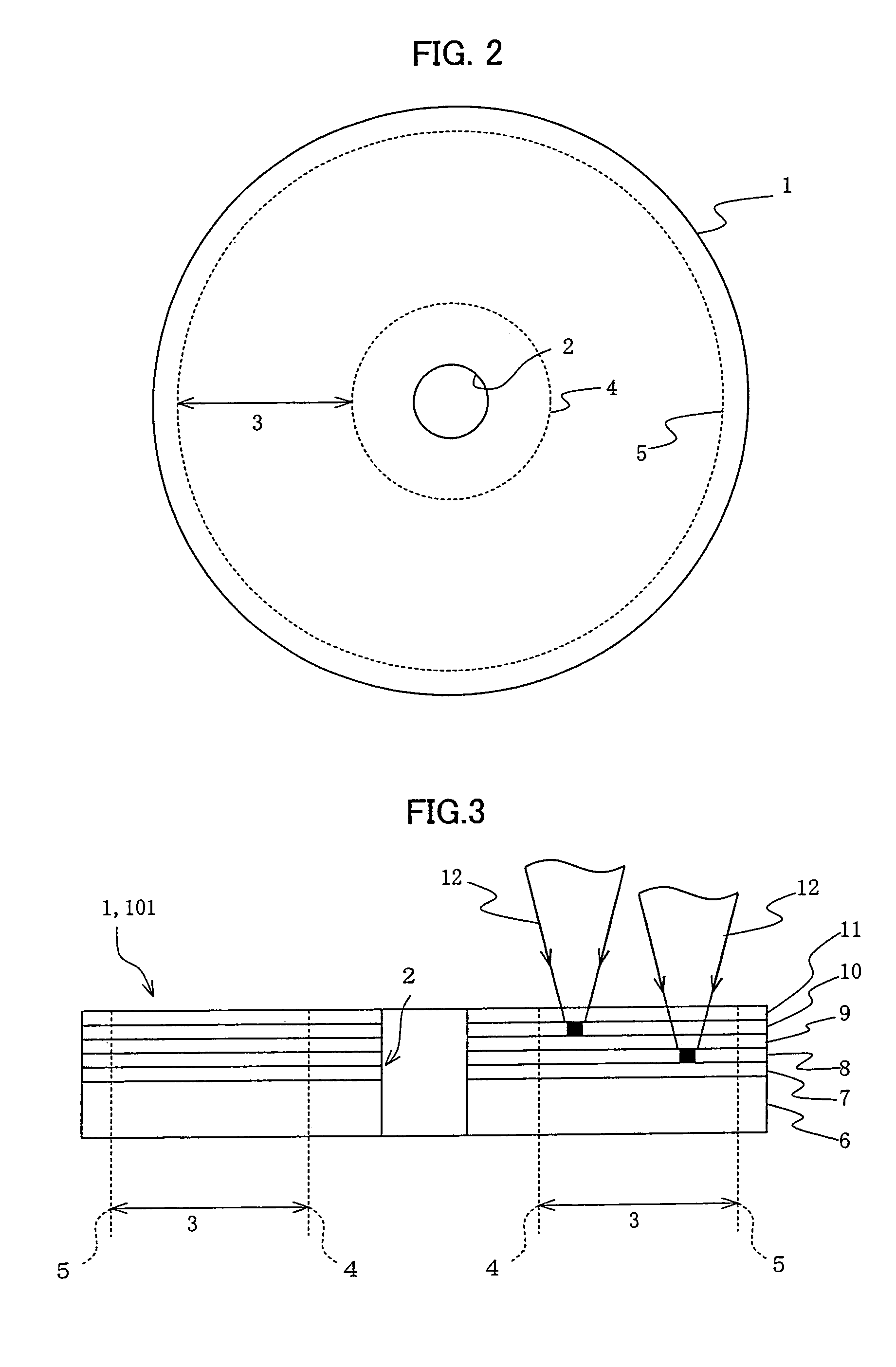
[0122]Referring to FIG. 2, an optical disk (optical storage medium) 1 of the present embodiment has a center hole 2 at its center and a recordable area 3 relatively close to the circumference in relation to the center hole 2. On the recordable area 3, a spiral read / write guiding groove is formed enabling data readout and write. Broken lines in the figure indicate an innermost part (portion) 4 and an outermost part (portion) 5 of the recordable area 3.

[0123]Referring to FIG. 3 showing a vertical cross-sectional view of the optical disk 1, the disk 1 has on a disk substrate 6 a guiding-groove-formed layer 7, a second storage layer (second data storage layer) 8, a guiding-groove-formed intermediate layer 9, a first storage layer (first data storage layer) 10, and a surface-coating layer 11, all the layers being stacked in this order. To read / write data in the first storage l...

embodiment 2

[Embodiment 2]

[0153]The following will describe another embodiment of the present invention in reference to FIGS. 9–11. An optical disk 61 of the present embodiment is operational with the optical-disk-read / write apparatus 31 which works as described in the foregoing.

[0154]The optical disk 61 of the present embodiment has extended areas 62 in the innermost part (portion) 4a and the outermost part (portion) 5a of the recordable area 3a of the first storage layer 10 as shown in FIGS. 9, 10. Therefore, the innermost part (portion) 4a of the first storage layer 10 extends further inwards in relation to the diameter of the optical disk 1 when compared to the innermost part 4b of the second storage layer 8. The outermost part (portion) 5a of the first storage layer 10 extends further outwards in relation to the diameter when compared to the outermost part 5b of the second storage layer 8.

[0155]In other words, the recordable area 3a of the first storage layer 10 is greater than the area of...

embodiment 3

[Embodiment 3]

[0166]The following will describe a further embodiment of the present invention in reference to FIGS. 12–20. An optical disk 71 of the present embodiment is operational with the optical-disk-read / write apparatus 31 which works as described in the foregoing.

[0167]The optical disk 61 has an extended area 62 in the innermost part 4a and the outermost part 5a of the recordable area 3a of the first storage layer 10. The optical disk 71 of the present embodiment has a fully prerecorded pseudo-recording area 72 in an area which is an equivalent of the extended area 62 as shown in FIGS. 12, 13. Therefore, on the optical disk 71 of the present embodiment, the recordable area 3 where ordinary information is recorded is as great on the first storage layer 10 as it is on the second storage layer 8. The pseudo-recording area 72 may be provided before the optical disk 71 is shipped out, for example.

[0168]In the arrangement, to perform normal read / write on the optical disk 71, simila...


PUM


Abstract

An optical read / write apparatus causes a read / write light beam from illuminating means to strike only one side of an optical storage medium including stacked data storage layers each of which is readable / writeable separately from the other layers. In this case, the optical read / write apparatus operates so that data is read / written from / into a second data storage layer after fully recording a recordable area of a first data storage layer. Thus, light can be shone with uniform intensity across the substantially entire recordable area of the second data storage layer without using a complex read / write system even under such conditions that the transmittance to light of the first data storage layer in the recordable area may vary depending on whether any data is recorded in the recordable area.

Description

FIELD OF THE INVENTION[0001]The present invention relates to optical storage media having a plurality of writeable and / or readable data storage layers, optical read / write apparatus using such media, and optical read / write method using such media.BACKGROUND OF THE INVENTION[0002]Recent years have seen on-going development of optical read / write apparatus capable of writing a large amount of data, like video data in digital format, and randomly accessing such data. Also, various attempts are being made to increase the storage density of optical disks used as storage media in such optical read / write apparatus.[0003]In optical read / write apparatus, attempts are being made to increase storage density by means of, for example, an increased numerical aperture of an objective lens and the use of short wavelength illumination for a smaller light beam spot. The efforts have been successful and the storage capacity optical disks are getting larger year after year. Technology has already establi...

Claims


Application Information

Patent Timeline
IPC IPC(8): G11B7/24G11B7/00G11B7/0045G11B7/007G11B7/125G11B7/24038G11B7/26G11B20/00
CPCG11B7/0045G11B7/007G11B7/00745G11B7/126G11B7/1267G11B7/24G11B7/24038G11B20/00086G11B20/00195G11B20/0021G11B20/00253G11B7/00454G11B2007/0013G11B7/00718G11B7/263
Inventor HIROKANE, JUNJIIWATA, NOBORU
Owner SHARP KK
Learn More