Command queueing engine

a command queue and engine technology, applied in the command field, can solve the problems of increasing the physical requirement and cost of the data controller b>150/b>, the use of firmware, and the increase of the storage space associated with the data controller, so as to reduce the delay, reduce the disk seek time, and reduce the latency of the bus command respons

Inactive Publication Date: 2007-02-20
BROADCOM INT PTE LTD
View PDF47 Cites 27 Cited by
  • Summary
  • Abstract
  • Description
  • Claims
  • Application Information

AI Technical Summary

Benefits of technology

[0010]the CQE 215 also provides assistance for the firmware to re-order queued commands. By default, the CQE 215 handles commands in the order they arrive. However, the firmware receives the interrupts required to allow re-ordering of the commands into sequential threads or for the purpose of reducing disk seek times. The firmware can manage multiple TE lists to optimize how sequential threads are built as commands arrive. Random commands or non-Read/Write commands are merged into the TE list such that the microprocessor can handle those commands in the time frame it determines as appropriate.
[0011]The present invention provides automated recognition and linking of commands belonging to a common thread, i.e., are sequential. T

Problems solved by technology

Use of firmware, however, requires increased storage space associated with the data controller.
As a result, the physical requirement and cost of data controller 150 are increased.

Method used


Image

  • Command queueing engine
  • Command queueing engine
  • Command queueing engine

Examples


Embodiment Construction

[0024]While this invention is susceptible of embodiment in many different forms, there is shown in the drawings and will be described herein in detail a specific embodiment thereof with the understanding that the present disclosure is to be considered as an exemplification of the principles of the invention and is not to be limited to the specific embodiment described.

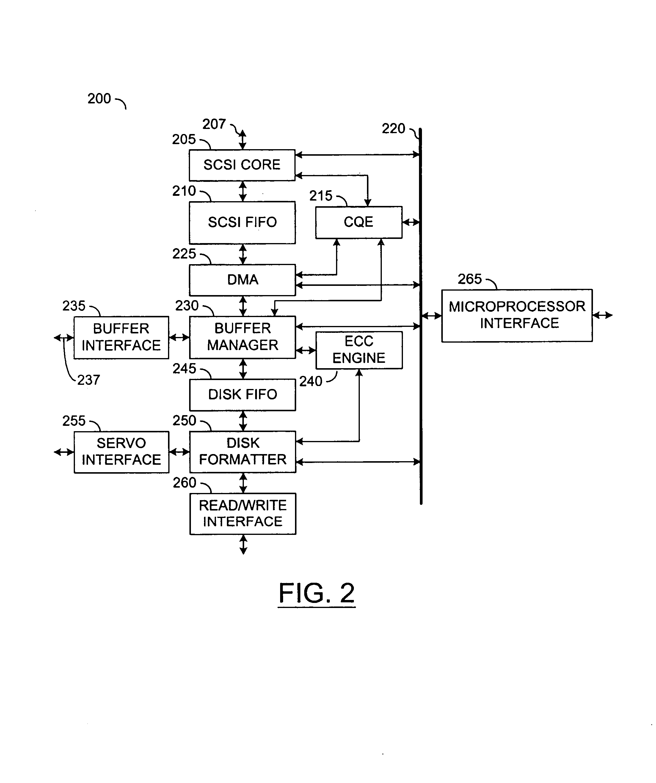
[0025]FIG. 2 shows a block diagram of a data controller 200 according to the present invention. Data controller 200 can be substituted for data controller 150 in FIG. 1. Data controller 200, which is used in a hard drive, preferably includes a SCSI core 205 that is coupled to a SCSI peripheral bus (e.g., bus 180 in FIG. 1) via a bus 207. SCSI core 205 is also coupled to a SCSI FIFO 210, a command queuing engine (“CQE”) 215 and a bus 220. A DMA block 225 is coupled to SCSI FIFO 210, CQE 215, bus 220 and a buffer manager 230. Buffer manager 230 is coupled to buffer interface 235, ECC engine 240, disk FIFO 245 and bus 220...


PUM


Abstract

The present invention includes a Command Queuing Engine (CQE) that is a firmware-assist block which processes some of the firmware tasks related to command and context management preferably for SCSI. When enabled, CQE will decode SCSI commands as they arrive, and determine if DMA contexts can be automatically configured and started to transfer the data for those commands. CQE can also program DMA contexts to automatically return status information either after the disk has completed a transfer (as in non-cached writes) or after the DMA transfer is completed (as in reads or cached writes). CQE also utilizes a buffer-based linked-list to queue the SCSI commands as they arrive for future DMA context configuration. The present invention provides automated recognition and linking of commands belonging to a common thread, i.e., are sequential. The present invention also provides extensive thread boundary information and flexible firmware control for reordering commands. Automatic TE entry generation and storage to buffer memory, and automatic TE retrieval from the buffer memory and execution of entire command threads are further features provided by the present invention. As a result, bus command response latency is decreased by reducing the delay for the command to be started and at the end of the data transfer for status to be send. Disk efficiency is increased by reducing the latency to back-fill or empty a buffer memory segment of data that will be transferred. Furthermore, the present invention is a low-cost trade-off between hardware and firmware functionality.

Description

FIELD OF THE INVENTION[0001]The present invention relates to a firmware assist block and more particularly to hardware that performs firmware tasks related to command and context management of a data controller.BACKGROUND OF THE INVENTION[0002]A data controller is included in the electronics of a peripheral device such as a CD-ROM or a hard drive. In FIG. 1, a peripheral device 100 is coupled to a host adapter board (“HAB”) 110 included in a host 120. Peripheral device 100 includes a data storage medium 130 that is coupled to a servo and read / write channel 140. Servo and read / write channel 140 is coupled to a data controller 150 and a microprocessor 160. Data controller 150 is coupled to buffer memory illustrated as a RAM 170 and a peripheral bus 180. Another memory, shown as SRAM 190, is coupled to microprocessor160 as local storage.[0003]The general function of data controller 150 is to process commands from a requester or initiator, such as host 120. Host 120 can be a personal co...

Claims


Application Information

Patent Timeline
IPC IPC(8): G06F13/14G06F13/28
CPCG06F13/28
Inventor ELLIS, JACKSON L.NOELDNER, DAVID R.SPRINGBERG, DAVID M.WESTON-LEWIS, GRAEME M.
Owner BROADCOM INT PTE LTD
Why Eureka
Try Eureka