Beaded jewelry mandrel and method of jewelry assembly

a technology of jewelry mandrels and beads, which is applied in the direction of mechanical measuring arrangements, instruments, diagnostic recording/measuring, etc., can solve the problems of complicated jewelry making, time and waste of materials, and complicated jewelry making to fit the wearer, so as to avoid repeated assembly and disassembly of the article, and reduce shipping costs. , the effect of low shipping cos

Inactive Publication Date: 2007-02-27
HAUG CHERI MARIE
View PDF32 Cites 12 Cited by
  • Summary
  • Abstract
  • Description
  • Claims
  • Application Information

AI Technical Summary

Benefits of technology

[0047]The mandrel can be made of a transparent material with the indicia imprinted on the interior surface and visible through the exterior. Instead of a megaphone shape, the mandrel can also be made in a cone shape, a terraced cone, a terraced megaphone, a series of cylinders or a jelly roll shaped device that rolls upon itself. Regardless of its shape, the purpose of the beaded jewelry mandrel is to serve as a designers model for sizing the finished article and avoid the need for the intended wearer to be present for repeated fittings.
[0063]It is an object of the present invention to aid in high volume production of articles of beaded jewelry.

Problems solved by technology

This results in wasted time and wasted materials.
The problem is more troublesome when making many different bracelets with different size beads.
The problem of making a piece of beaded jewelry to fit the wearer is also complicated by the fact that beads are available in numerous diameters.
Using a printed chart that correlates bead size to finished bracelet size is rendered useless because jewelry is often made with a mix of bead sizes.
As those familiar with the art of jewelry making will appreciate, working out a mathematical equation is simply too tedious.
And the problem is further complicated by the fact that long cylindrical beads will necessitate a longer bracelet whose length is virtually impossible to determine by way of a mathematical equation.
This is likely owing to the fact that a solid metal bracelet would be uncomfortable to wear considering the movement of the ankle muscles and tendons.
Existing bracelet mandrels are made of metal suitable for hammering or applying heat, and are simply too clumsy and heavy for a beading artist's purpose. http: / / shorinternational.com / MandrelRingBracelet.ht
There does not exist a mandrel suitable for beaded articles of jewelry.
The problem faced by the jewelry designer is determining the finished circumference of a product that is constructed in a linear fashion.
Beaded bracelets on the other hand are not so easily adjusted.
The bracelet mandrels in the prior art do not accommodate this range of sizes.
The difficulty with such a chart is that any given bracelet, anklet or necklace may typically be made with beads of several different sizes.
Working out a mathematical equation using the “Pi R squared” formula can be complicated and time consuming and beyond the skill and patience of many bead artists.
Factoring in the conversion from metric to English only adds another level of difficulty.
This resulted in frequent mistakes wherein a bracelet was either too small or too large for the intended wearer.
This in turn resulted in a waste of beading materials and time.
The problem is amplified when the designer is making jewelry professionally and in high volume.
The problem is even greater when one is doing business over the internet and the customer must mail the bracelet back to the designer to be remade.
Regardless of one's level of experience in jewelry making, the sizing problem remains because bracelets can be made in an infinite variety of sizes using an infinite variety of shapes and sizes of beads.
But none of the devices available serve as a body form to help the designer analyze the circumference of beaded jewelry and facilitate the making of adjustments.
Metal mandrels are utterly useless to the beaded jewelry designer.
So, in order to keep the metal mandrel small enough to place on a metal smith's workbench, the mandrel can only accommodate a few sizes.

Method used


Image

  • Beaded jewelry mandrel and method of jewelry assembly
  • Beaded jewelry mandrel and method of jewelry assembly
  • Beaded jewelry mandrel and method of jewelry assembly

Examples


Embodiment Construction

Nomenclature

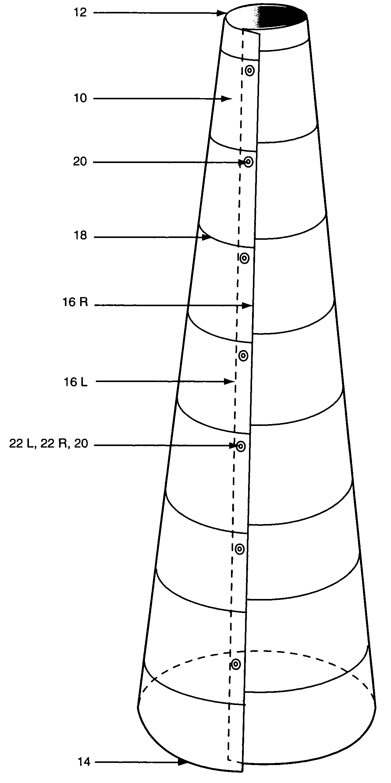
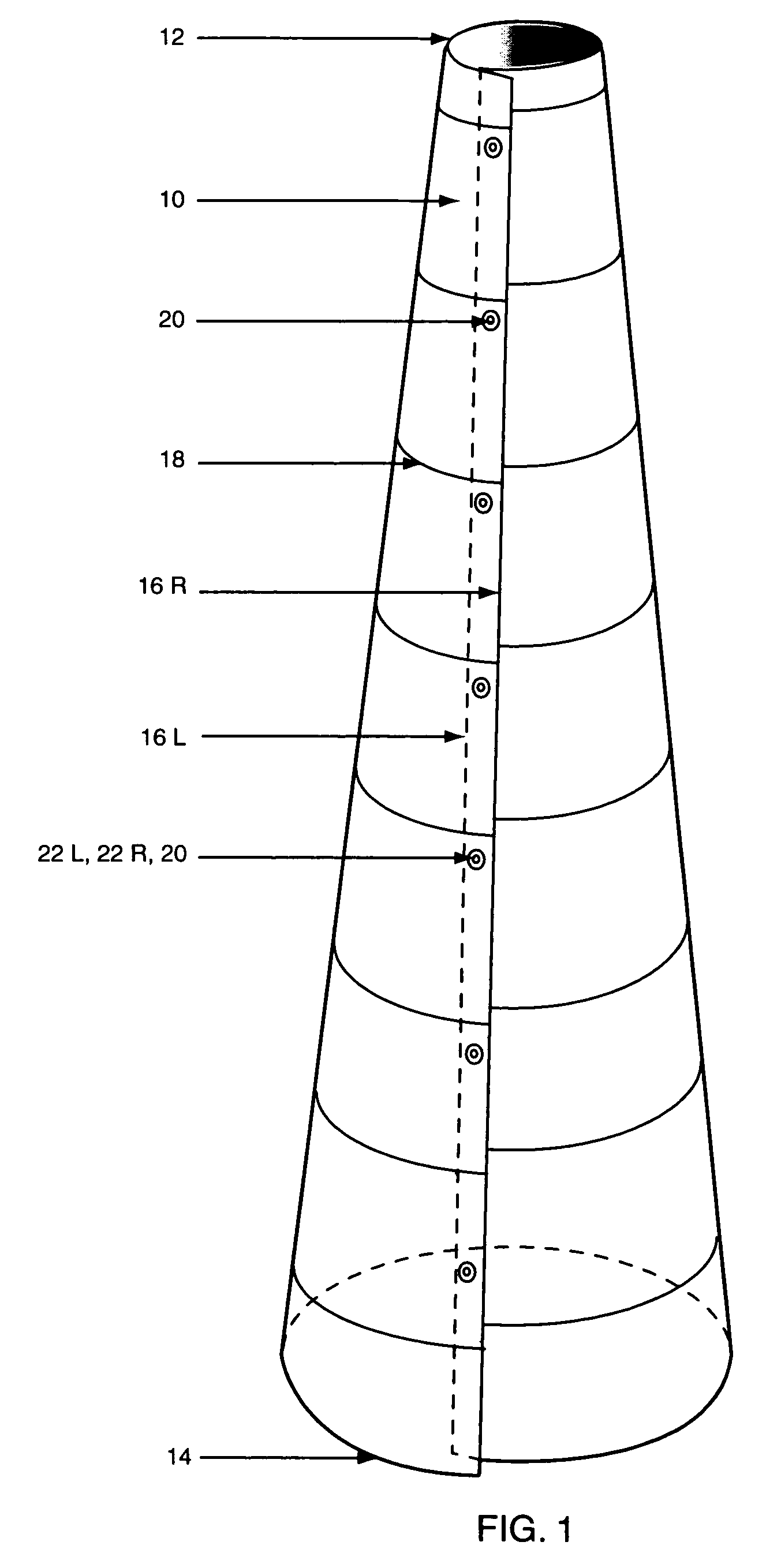
[0079]10 Beaded Jewelry Mandrel

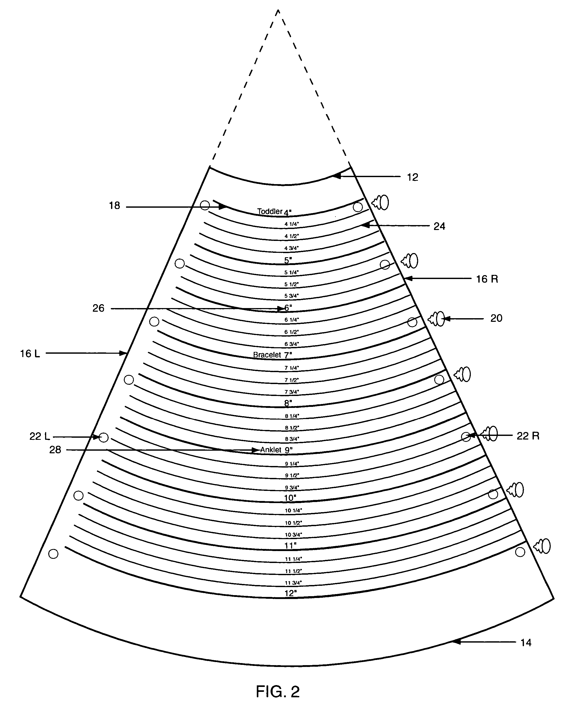
[0080]12 Top Edge, First Radius

[0081]14 Bottom Edge, Second Radius

[0082]16R and 16L Straight Overlapping Edges

[0083]18 Inscribed Parallel Arced Lines

[0084]20 Buttons Holding the Device Together

[0085]22L and 22R Through Holes Associated with Buttons

[0086]24 Inscribed Parallel Arced Lines at one quarter inch intervals

[0087]26 Measurement Indicia

[0088]28 Inscribed Indicia Indicating Jewelry Items and Body Parts

[0089]30 Human Wrist

[0090]32 Bead Radius

[0091]34 Bracelet Diameter

[0092]36 First Bead

[0093]38 Bracelet

[0094]40 Second Bead

[0095]42 Wrist Diameter

[0096]46 Wrist Circumference

[0097]48 Bracelet Circumference and Bracelet Length

[0098]50 Beading Wire

[0099]52 Bead Hole

[0100]54 Short Opposing Side

[0101]56 Short Opposing Side

[0102]58 Long Opposing Side

[0103]60 Long Opposing Side

[0104]62 Arrow

[0105]64 Inscribed Measuring Indicia

Construction

[0106]For convenience, the term “bracelet” is used generically herein to include any article of beaded jewel...


PUM


Abstract

A method for making beaded jewelry is provided. The method utilizes a megaphone shaped device having a small diameter first end and a larger diameter second end. The circumference of the first end is that of one part of the human body, such as a child's wrist. The circumference of the second end is the size of another part of the human body, such as an adult ankle. Markings on the girth of the device sequentially graduate in circumference and define graduated bracelet, anklet and other jewelry sizes. When one is making a bracelet or other article of jewelry of strung beads, the diameter of the beads affects the finished length of the article. Use of the device takes into account the diameters of the beads and thereby ensures that the finished item of beaded jewelry will fit the intended wearer.

Description

CROSS-REFERENCE TO RELATED APPLICATIONS, IF ANY[0001]This application claims the benefit under 35 U.S.C. §119(e) of co-pending provisional application Ser. No. 60 / 496,719, filed 20 Aug., 2003. Application Ser. No. 60 / 496,719 is hereby incorporated by reference.STATEMENT REGARDING FEDERALLY SPONSORED RESEARCH OR DEVELOPMENT[0002]Not applicable.REFERENCE TO A MICROFICHE APPENDIX, IF ANY[0003]Not applicable.BACKGROUND OF THE INVENTION[0004]1. Field of the Invention[0005]The present invention relates in general to a mandrel to aid in the construction of beaded bracelets, ankle bracelets, necklaces, head bands, thigh garters and upper arm bracelets.[0006]2. Background Information[0007]In the jewelry arts, beads are strung on cords comprised of, for example, monofilament, or jewelry wire. An interengaging but releasable cooperating clasp pair is attached and the strand of beads forms a closed loop to become an article of jewelry, such as a necklace or bracelet.[0008]In constructing an ite...

Claims


Application Information

Patent Timeline
Patent Type & Authority Patents(United States)
IPC IPC(8): G01B3/34A44C27/00G01B5/02
CPCG01B5/025A44C27/00
Inventor HAUG, CHERI MARIE
Owner HAUG CHERI MARIE
Why Eureka
Try Eureka