Sludge harvester for removing sludge from sludge ponds

a technology of sludge harvester and sludge pond, which is applied in the direction of filtration separation, liquid displacement, separation process, etc., can solve the problems of increased agitation and achieve the effect of high nutrient content and low cost of operation

Inactive Publication Date: 2007-02-27
CRYSTAL PARK TECH
View PDF25 Cites 8 Cited by
  • Summary
  • Abstract
  • Description
  • Claims
  • Application Information

AI Technical Summary

Benefits of technology

[0014]The present invention is directed to a sludge harvester for removing a concentrated nutrient sludge from sludge ponds. The harvester is intended to be relatively inexpensive from an equipment cost perspective, as well as relatively inexpensive to operate, while allowing the user to retrieve a high nutrient sludge product from sludge ponds so as to yield a valuable fertilizer product.
[0016]The means for gently breaking up at least a portion of the sludge layer may comprise any mechanical device capable of gently breaking up a portion of the sludge layer. According to one embodiment, the means for gently breaking up at least a portion of the sludge layer comprises a pin mixer, an auger, or a rake. The means for gently breaking up a portion of the sludge layer is intended to just break up the surface of the sludge layer without overly agitating the material of the sludge layer with the adjacent liquid dilute layer. By keeping agitation to a minimum, the nutrient value of the recovered product is maintained at a high level.
[0018]According to one embodiment, the frame of the harvester includes a plurality of sideboards to further reduce turbulence and column mixing between the sludge layer and the dilute layer. Sideboards also substantially prevent vortexing of the dilute layer into the pump.

Problems solved by technology

Because the sludge layer is gently broken up and over agitation is undesirable, the pump preferably removes the sludge at a reduced rate as compared to alternative devices and techniques.
For comparison sake, traditional dredging devices operate at about 800 gpm, resulting in greatly increased agitation.

Method used


Image

  • Sludge harvester for removing sludge from sludge ponds
  • Sludge harvester for removing sludge from sludge ponds
  • Sludge harvester for removing sludge from sludge ponds

Examples


Embodiment Construction

I. Introduction

[0026]A detailed description of the invention will now be provided with specific reference to figures illustrating preferred embodiments of the invention. It will be appreciated that like structures will be provided with like reference designations.

[0027]The present invention is directed to a sludge harvester for removing a concentrated nutrient sludge from sludge ponds. The harvester is intended to be relatively inexpensive to operate, while allowing the user to retrieve a high nutrient sludge product from sludge ponds so as to yield a valuable fertilizer product.

II. An Exemplary Sludge Harvester

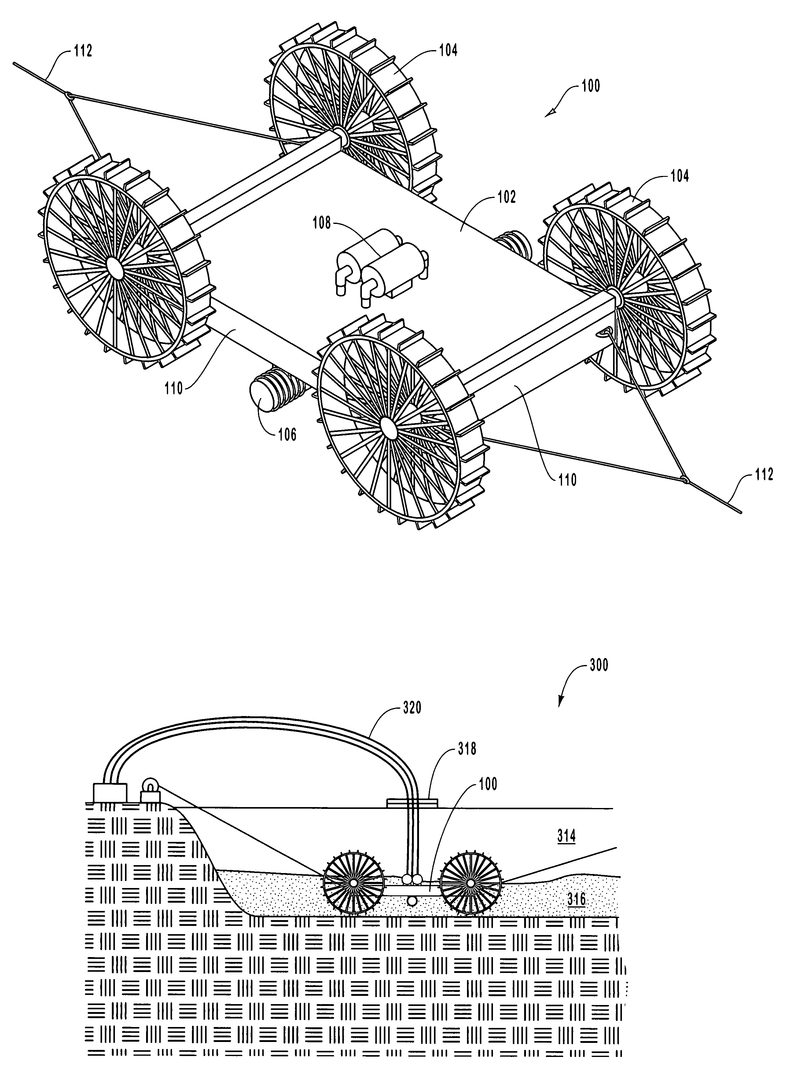
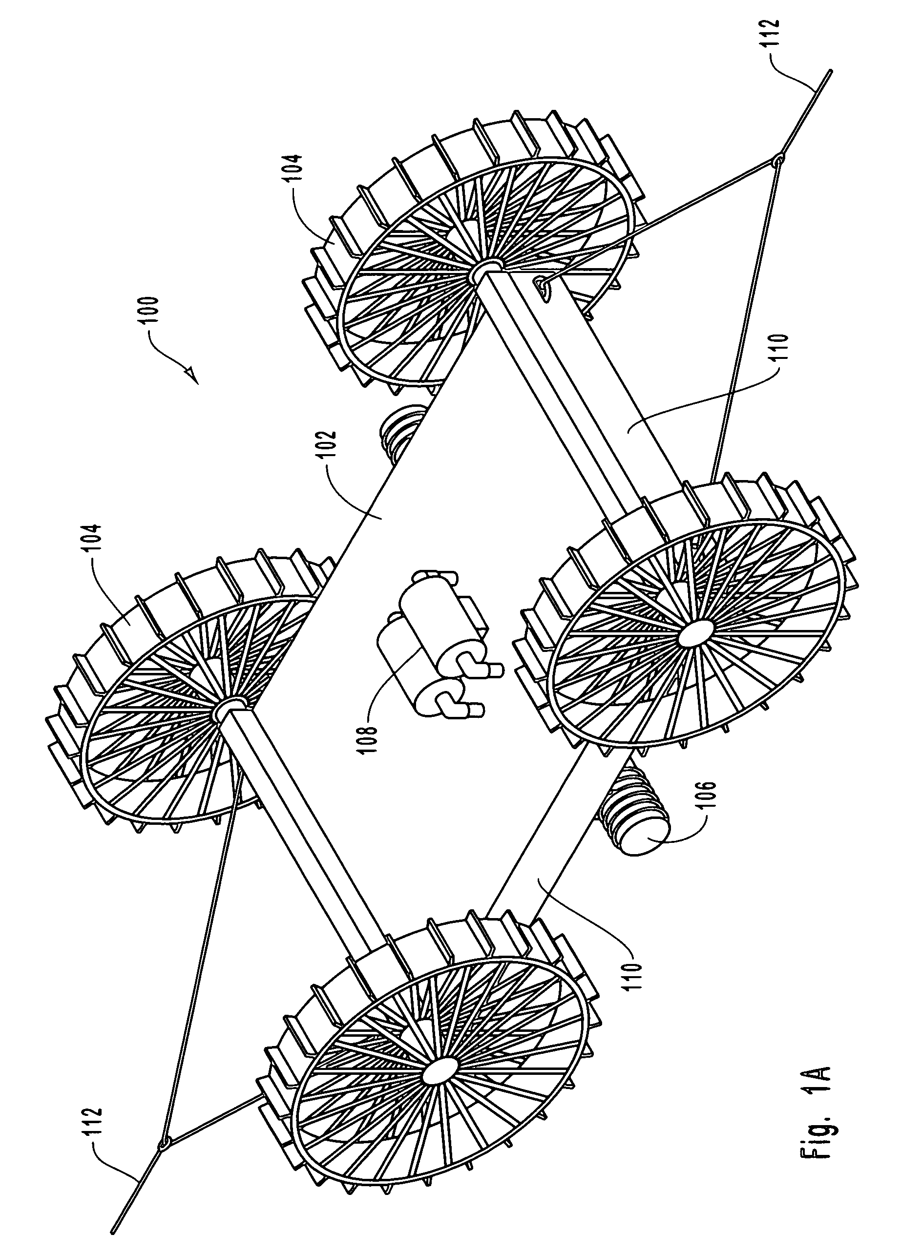
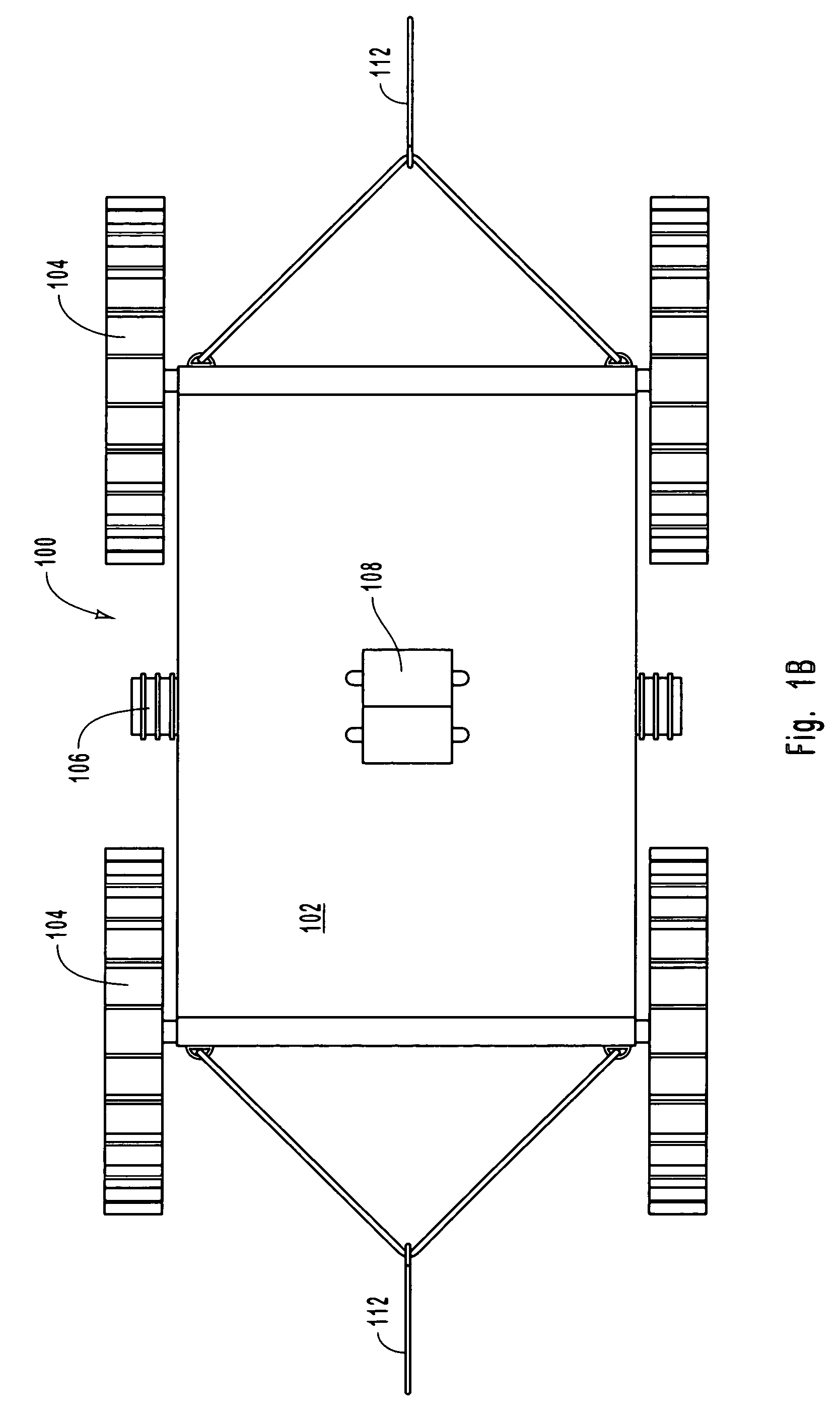
[0028]FIGS. 1A and 1B illustrate an exemplary embodiment of a sludge harvester according to the present invention. The sludge harvester 100 includes a frame 102, a plurality of wheels 104, a pin mixer 106, and a pump 108, and a plurality of sideboards 110.

[0029]In the illustrated embodiment, the frame 102 comprises a flat bed, while the wheels 104, the pin mixer 106, and the ...


PUM

PropertyMeasurementUnit
outer perimeteraaaaaaaaaa
volumeaaaaaaaaaa
concentrationaaaaaaaaaa

Abstract

A sludge harvester for removing a concentrated nutrient sludge from a sludge pond includes a frame, one or more wheels or skids attached to the frame, means for gently breaking up at least a portion of the sludge layer adjacent to a dilute layer, and means for capturing at least a portion of the broken up sludge layer. The organic sludge product recovered by the harvester has a higher nutrient concentration as compared to alternative methods because of minimized mixing of the sludge and dilute layers during collection of the organic sludge product. The organic sludge product captured by the harvester can be applied directly to agricultural land or used in the production of a certifiable organic or other fertilizer.

Description

BACKGROUND OF THE INVENTION[0001]1. The Field of the Invention[0002]The present invention relates generally to removal of organic-based wastes from sludge ponds. More specifically, the present invention relates to devices for removing sludge from sludge ponds, which sludge may then be directly applied to agricultural land, or used to produce organic fertilizers by processing the organic-based sludge.[0003]2. The Relevant Technology[0004]Feedlots, animal barns, municipal sewage, and farms that keep large numbers of animals are sources of enormous quantities of organic waste. The expression “organic waste source” will hereinafter refer to any of these sources of organic waste or to any source that similarly produces organic waste, although perhaps in different quantities or by different activities.[0005]The disposal of untreated organic waste causes serious pollution problems which include those due to the waste's high content of chemically oxidizable components and biochemically deco...

Claims


Application Information

Patent Timeline
Patent Type & Authority Patents(United States)
IPC IPC(8): E02F3/00A01C3/04B01D21/00B08B9/08E02F3/88E02F3/92
CPCA01C3/04E02F3/9256E02F3/8875B08B9/08
Inventor SOWER, LARRY P.
Owner CRYSTAL PARK TECH
Why Eureka
Try Eureka