Vehicle drive force control apparatus

a technology of drive force control and control apparatus, which is applied in the direction of machine/engine, process and machine control, electric devices, etc., can solve the problems of electric generators temporarily being unable to deliver the required voltage to electric motors, situation will occur, etc., to curb the decline of generator output, increase the gear ratio of a transmission, and expand the operating range

Active Publication Date: 2007-02-27
NISSAN MOTOR CO LTD
View PDF10 Cites 9 Cited by
  • Summary
  • Abstract
  • Description
  • Claims
  • Application Information

AI Technical Summary

Benefits of technology

[0008]The present invention was conceived in view of this shortcoming. One object of the present invention is to provide a vehicle drive force control apparatus that is capable of expanding the operating range in which the electric motor can be driven in a stable manner.
[0009]In order to resolve the aforementioned shortcoming, the present invention proposes a vehicle drive force control apparatus that is configured such that when it is determined that the generator output voltage required by the electric motor cannot be obtained, the amount of acceleration slippage permitted at the main drive wheel or main drive wheels is increased so as to curb the decline in generator output.
[0010]In view of the foregoing, a vehicle drive force control apparatus is provided that basically comprising a main drive source, an electric generator, an electric motor, a main drive source output suppressing section, and an acceleration slippage degree revising section. The main drive source is configured and arranged to drive a main drive wheel. The electric generator is configured and arranged to be driven by the main drive source. The electric motor is configured and arranged to drive a subordinate drive wheel from output voltage supplied from the electric generator. The main drive source output suppressing section is configured to suppress the output of the main drive source such that a degree of acceleration slippage of the main drive wheel is matched to a preset target slippage degree when the main drive wheel undergo acceleration slippage. The acceleration slippage degree revising section is configured to increase the target slippage degree upon estimating that at least one of a target generator output voltage will likely be insufficient to achieve a target motor output of the electric motor, and a gear ratio of a transmission has increased.

Problems solved by technology

Since the voltage supplied to the electric motor is affected by the rotational speed of the engine driving the electric generator, there is the possibility that a situation will occur in which the electric generator is temporarily unable to deliver the required voltage to the electric motor, e.g., when the transmission upshifts from first speed to second speed.

Method used


Image

  • Vehicle drive force control apparatus
  • Vehicle drive force control apparatus
  • Vehicle drive force control apparatus

Examples


first embodiment

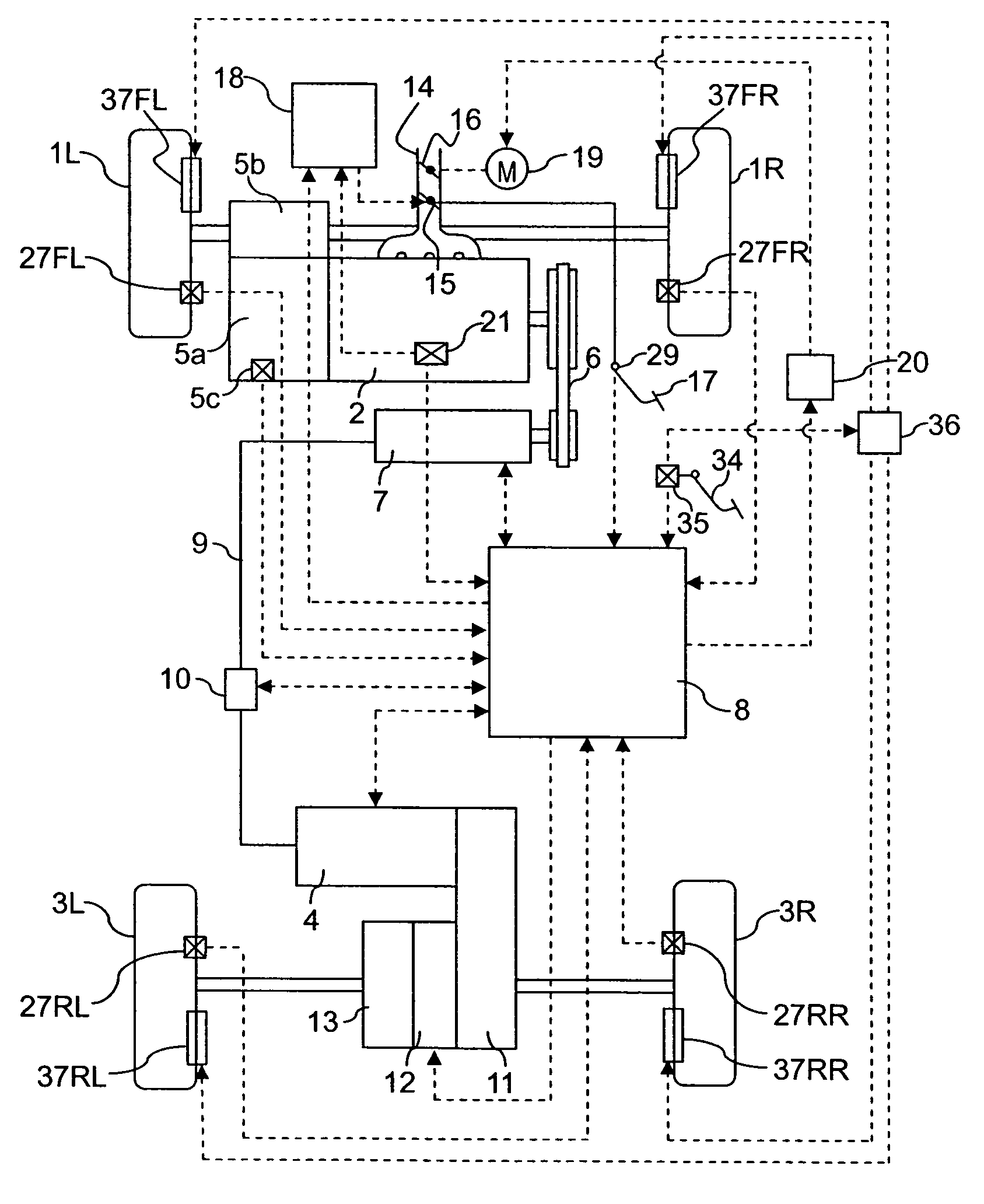
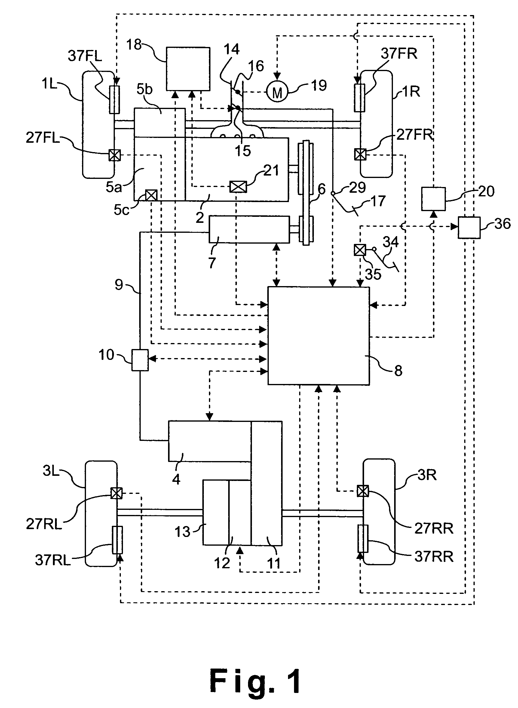
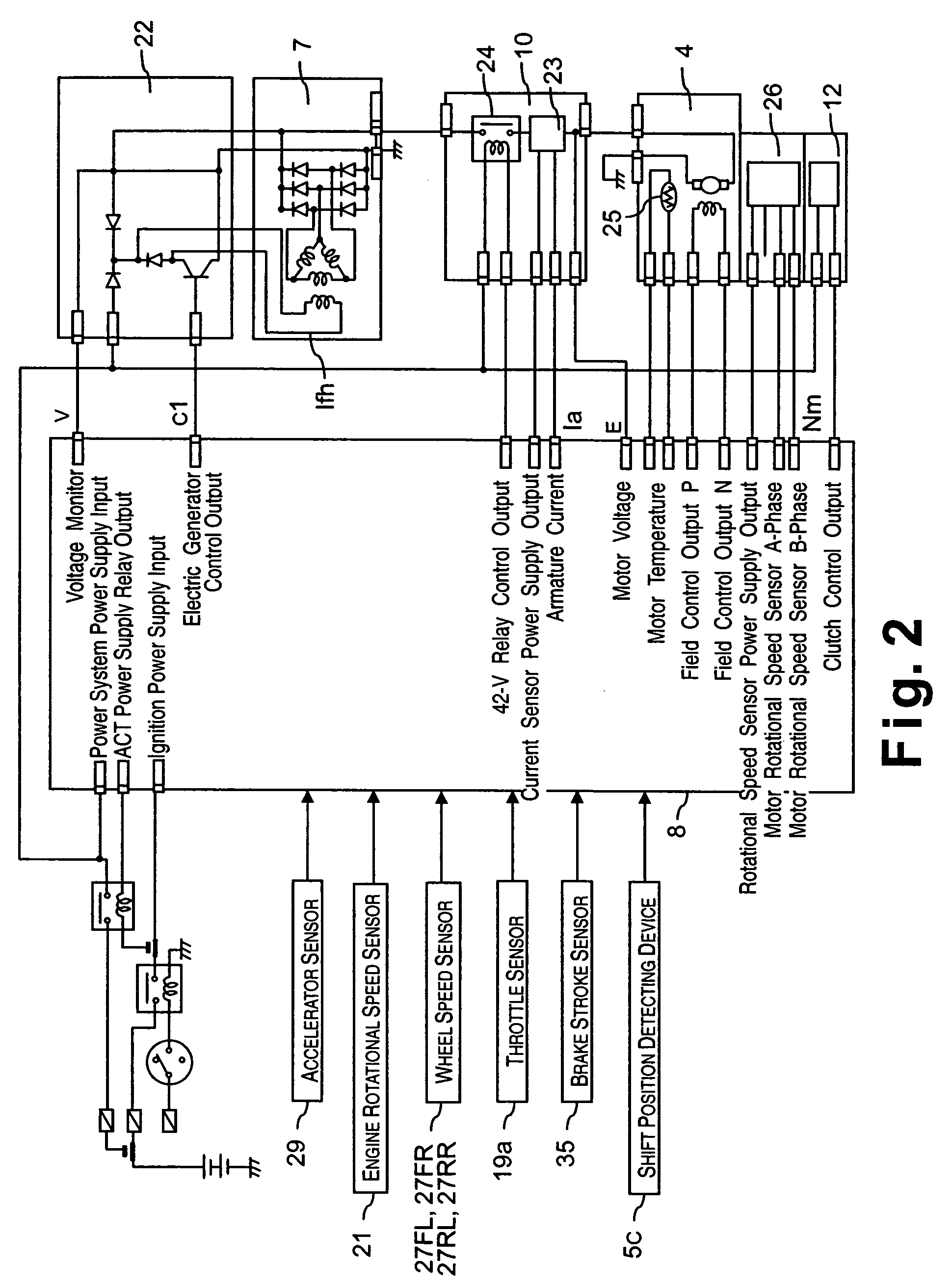
[0026]Referring initially to FIGS. 1–11, a vehicle driving force control apparatus will now be explained in accordance with a first embodiment of the present invention. As seen in FIG. 1, a four wheel drive vehicle is diagrammatically illustrated that is equipped with the vehicle driving force control apparatus in accordance with the present invention. As shown in FIG. 1, the vehicle in accordance with this embodiment has left and right front wheels 1L and 1R that are driven by an internal combustion engine or main drive source 2, and left and right rear wheels 3L and 3R that are driven by an electric motor or subordinate drive source 4, which is preferably a direct current (DC) electric motor. Thus, the front wheels 1L and 1R serve as the main drive wheels, while the rear wheels 3L and 3R serve as the subordinate drive wheels. The output torque Te of the engine 2 is delivered to the left and right front wheels 1L and 1R after passing through a transmission 5a and a differential gea...

second embodiment

[0107]Referring now to FIG. 12, a vehicle driving force control apparatus in accordance with a second embodiment will now be explained. The configuration of the vehicle in this second embodiment is the same as the configuration of the vehicle in the first embodiment (see FIG. 1). In view of the similarity between the first and second embodiments, the parts or steps of the second embodiment that are identical to the parts or steps of the first embodiment will be given the same reference numerals as the parts or steps of the first embodiment. Moreover, the descriptions of the parts or steps of the second embodiment that are identical to the parts or steps of the first embodiment may be omitted for the sake of brevity. In other words, unless otherwise specified, the rest of the configuration of the vehicle and the processing in the second embodiment are the same as the configuration of the first embodiment. More specifically, the constituent features of the second embodiment are basica...


PUM


Abstract

A vehicle driving force control apparatus is configured to provide a vehicle drive force control apparatus that can expand the operating region within which an electric motor can be driven in a stable manner. The output of an engine is delivered to the main drive wheels through a transmission and also to an electric generator. The output voltage of the electric generator is supplied to the electric motor and the output of the electric motor drives the subordinate drive wheels. When it is determined that the generator output voltage will not be sufficient to meet the requirement of the electric motor, the amount of acceleration slippage allowed at the left and front wheels is increased.

Description

BACKGROUND OF THE INVENTION[0001]1. Field of the Invention[0002]The present invention generally relates to a vehicle drive force control apparatus for a vehicle having a wheel or set of wheels driven by a main drive source and an electric generator also driven by the main drive source. Preferably, an electric motor is driven with electric power generated by a generator that is driven by the main drive source. The present invention especially useful in an all wheel drive vehicle in which a pair of main drive wheels are driven by the main drive source, such as an internal combustion engine, and a pair of subordinate drive wheels are driven by the electric motor. Thus, the invention is particularly well-suited for a so-called battery-less four-wheel drive vehicle in which the engine drives the generator and the electric power from the generator is supplied to the electric motor.[0003]2. Background Information[0004]One example of a drive force control apparatus is disclosed in Japanese ...

Claims


Application Information

Patent Timeline
Patent Type & Authority Patents(United States)
IPC IPC(8): B60K17/35B60K6/34B60K6/44B60W20/00B60K6/52B60K6/54B60K17/356B60K28/16B60L3/10B60L11/00B60L50/15B60L50/16B60W10/06B60W10/08B60W10/18F02D29/00F02D29/02
CPCB60K6/44B60K28/16B60L3/102B60L11/12B60K6/52Y02T10/6265B60L2240/423B60L2240/486B60W2520/26B60W2540/16B60W2710/0644B60W2710/083Y02T10/623Y02T10/7077Y02T10/642B60L50/15Y02T10/62Y02T10/64Y02T10/7072B60K6/00
Inventor KAMATA, TATSUYASHIMIZU, KOUICHISAEKI, HIDEYUKIAOYAGI, MASANORI
Owner NISSAN MOTOR CO LTD
Why Eureka
Try Eureka