Ink jet recording apparatus

a recording apparatus and jet technology, applied in the direction of printing, other printing apparatus, etc., can solve the problems of reducing the collection efficiency of the solvent collection device, reducing the collection efficiency of the collection device, and affecting the effect reducing the influence of water vapor components, and efficiently removing solvent vapor

Active Publication Date: 2007-02-27
FUJIFILM HLDG CORP +1
View PDF11 Cites 17 Cited by
  • Summary
  • Abstract
  • Description
  • Claims
  • Application Information

AI Technical Summary

Benefits of technology

[0012]A primary object of the present invention is to solve the problems of the conventional techniques described above, and to provide an ink jet recording apparatus that is capable of selectively collecting air containing solvent vapor in a region in proximity to a fixing means that generates the largest quantity of solvent vapor, reducing an influence of a water vapor component in the collected air, efficiently removing the solvent vapor, miniaturizing the apparatus, reducing power consumption (achieving power saving), and improving maintainability, that is, achieving a stabilized operation of the apparatus.

Problems solved by technology

An organic solvent is used as the ink solvent component and the emission thereof to the outside of the apparatus leads to environmental pollutions.
However, the solvent collecting device used in the conventional ink jet recording apparatus takes in air in the entire region inside the ink jet recording apparatus, so that there is a problem that, in addition to air containing the solvent component, the solvent collecting device simultaneously takes in air containing a small quantity of the solvent component, such as the atmosphere (air in an installation environment) or the outside air flowing into the apparatus, and then a vapor concentration of the solvent component contained in the taken-in air is low, therefore the collection efficiency is decreased.
In particular, a water vapor component in the taken-in air causes lowering of the collection efficiency of the solvent collecting device that collects the vapor of the solvent component, which leads to various problems such as an increase in size of the solvent collecting device, an increase in power consumption, and lowering of maintainability.
Also, not only the solvent component but also the moisture is simultaneously collected, so that there is another problem that it takes a lot of trouble to reuse the solvent.
Further, the air in the entire region inside the apparatus is taken in, so that particularly when the heat of the heat-fixing portion is easily transmitted to the ejection head or when air from the heat-fixing portion flows to the ejection head, the ejection head is easily dried, which leads to still another problem that ink clogging occurs due to the drying of the ejection head or ink ejection stability is lowered due to changes in viscosity of the ink.
Therefore, there is a problem that the apparatus construction becomes complicated and the apparatus size is increased.
Also, the ink forming the image on the transfer drum is mainly composed of the color particles and it is difficult to completely remove the solvent component from the ink, therefore when the printer is continuously operated or a large amount of print is outputted, there is another problem that it is also required to remove the solvent component vaporized from images transferred onto recording media.
With the technique disclosed in JP 11-320856 A, however, in the case of the printer that circumvents a situation where vaporization of a solvent of ink ejected onto a print medium continues for a long time using the means for heating the ink on the print medium in a non-contact manner immediately after recording on the print medium transport path or the means for sucking air around a surface of the print medium immediately after recording, there is a problem that it is impossible to collect the ink solvent vaporized as a result of heating or sucking.
Also, in the case of the printer including the cover box that covers the whole of the print medium transport path or the ink ejection portion as well as the whole of the transport path, there is a problem that the apparatus construction becomes complicated and the apparatus increases in size.
Further, in the case of the printer that accelerates the ink solvent vaporization using the heating means or the sucking means provided immediately after the ejection head or the printer that uses the cover box that covers the whole of the print medium transport path and the ink ejection portion, there is a problem that drying of the ejection head or changes in viscosity of ejection ink may exert adverse effects.
Also, in the case of the printer including the means for forming the layer of the ink vaporization suppression agent on a print medium immediately after recording, there is a problem that the cost of outputted prints is increased.

Method used


Image

  • Ink jet recording apparatus
  • Ink jet recording apparatus
  • Ink jet recording apparatus

Examples


first embodiment

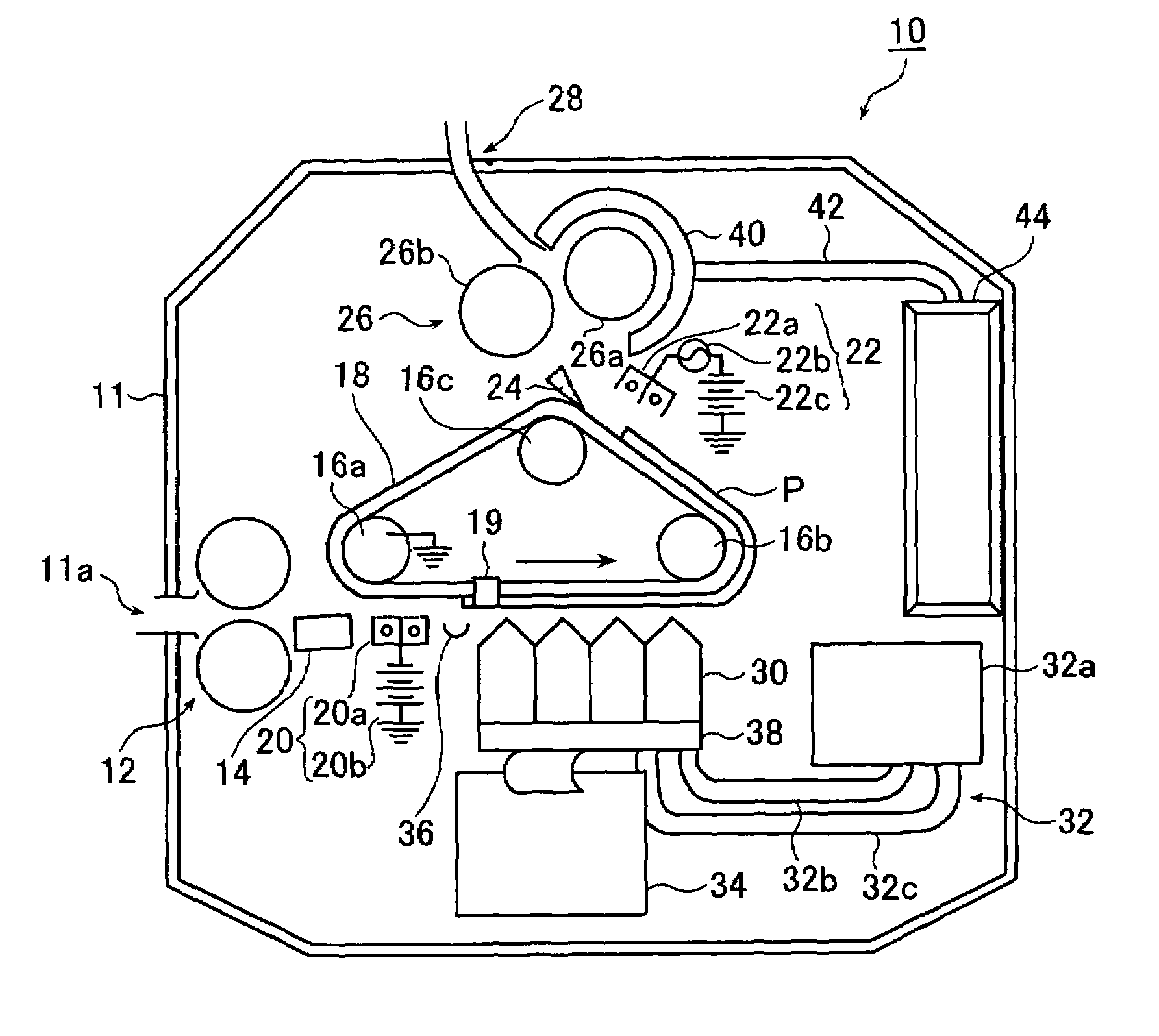
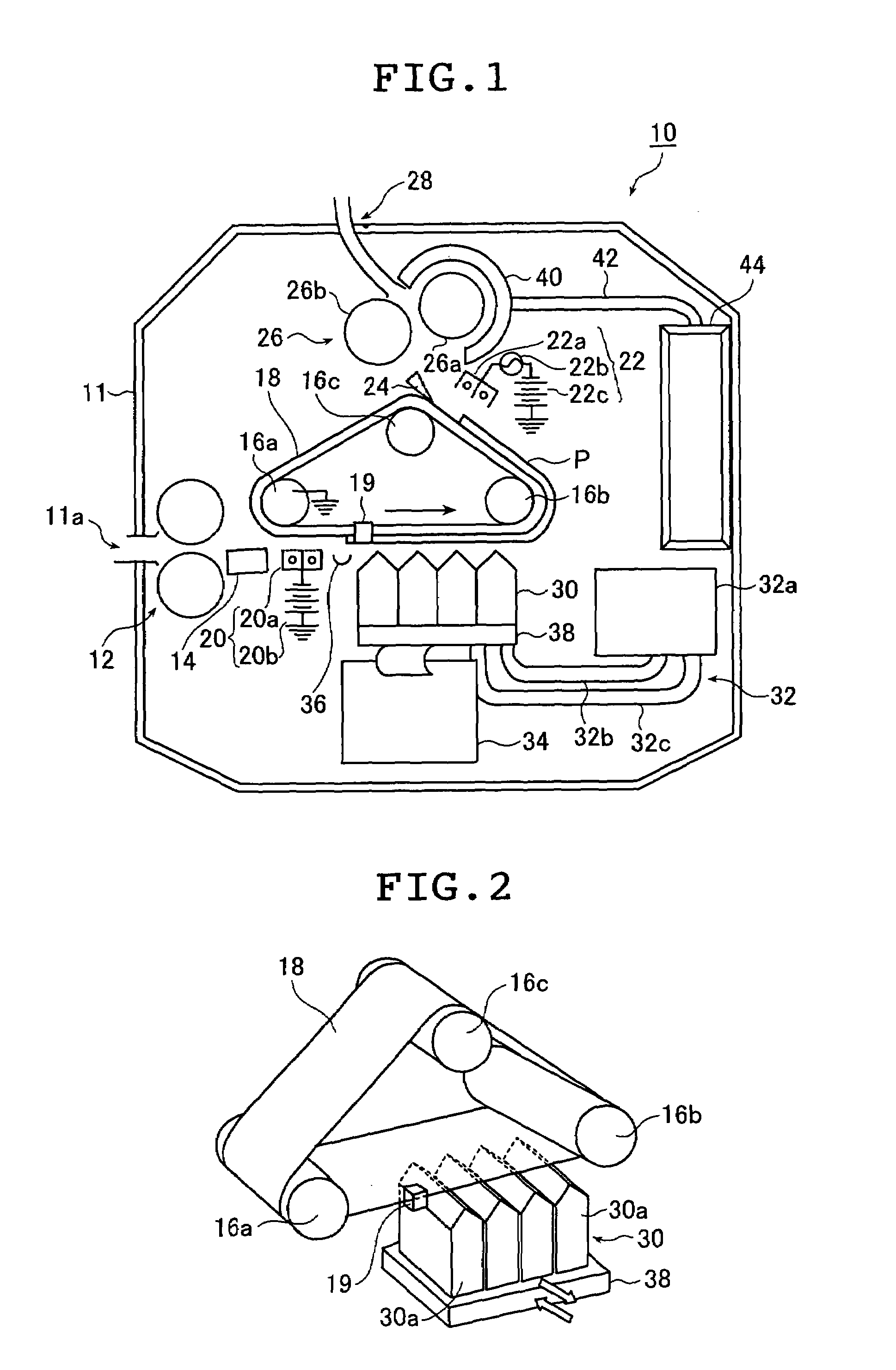
[0036]FIG. 1 is a schematic construction diagram showing an overall construction of the ink jet recording apparatus according to the present invention.

[0037]An electrostatic ink jet recording apparatus (hereinafter referred to as the “ink jet printer”) 10 shown in FIG. 1 records a full-color image by forming an image of ink particles (color particles) through ejection of ink droplets in four colors in accordance with inputted image data using an image forming means onto a recording medium P transported by a transport means and fixing the image of ink particles formed on the recording medium P. Also, the ink jet printer 10 collects air containing a large quantity of ink solvent vapor from a region in proximity to a fixing / transporting means 26 using a collecting means and removes the solvent in the collected air using a removing means.

[0038]The ink jet printer 10 shown in FIG. 1 is an apparatus that performs one-sided four-color printing on the recording medium P. For this purpose, a...

second embodiment

[0151]Next, the ink jet recording apparatus of the present invention will be described.

[0152]An ink jet printer 100 shown in FIG. 6 has approximately the same construction and function as the ink jet printer 10 shown in FIG. 1. However, the ink jet printer 100 differs from the ink jet printer 10 in that the recording medium P is not directly charged for image formation, an insulative transport belt 112 is used, a conductive platen 114 is used as the counter electrode of an ejection head 30, an electrostatic adsorption means 116 and a discharge means 117 that are each a conductive roller are used, a preliminary heating means 118 is provided between the discharge means 117 and a fixing / transporting means 26, and a blowing means 119 is provided in addition to a hood 40 and a duct 42 as a solvent-containing air collecting means. In the following description, the same construction elements as in the ink jet printer 10 are given the same reference numerals and different construction eleme...

third embodiment

[0162]It should be noted here that in order to maintain the distance between the ejection head 30 and the recording medium P transported by the transport belt 112 constant, in place of the above-mentioned method where the. conductive platen 114 is used, a tension member for having the transport belt 112 pass by a home position under a stretched state may be provided for the back surface of the transport belt 112 at a position opposing the ejection head 30. As the tension member, it is possible to use a conductive roller or the like, for instance. These constructions are also applicable to the ink jet printer 10 shown in FIG. 1 and each embodiment of the present invention such as a third embodiment to be described later.

[0163]The electrostatic adsorption means 116 is a grounded conductive roller and contacts a surface of the recording medium P fed by the feed roller 12, thereby removing electrical charges generated on the surface of the recording medium P through the transport belt 1...


PUM


Abstract

The ink jet recording apparatus includes an image forming device for forming an image on a recording medium by ejecting ink containing a solvent and color particles dispersed in the solvent, a fixing device for fixing the image formed on the recording medium by the image forming device, a collecting device for selectively collecting air containing the solvent from an atmosphere in proximity to the fixing device, and a removing device for removing the solvent from the solvent-containing air collected by the collecting device.

Description

BACKGROUND OF THE INVENTION[0001]1. Field of the Invention[0002]The present invention relates to a technical field of an ink jet recording apparatus that records an image on a recording medium by ink jet system using ink where color particles (colorant component) are dispersed in a solvent (dispersion medium). More specifically, the present invention relates to an ink jet recording apparatus that is capable of efficiently collecting solvent vapor generated from the ink.[0003]2. Description of the Related Art[0004]An electrostatic ink jet recording system is a system in which ink containing color particles, such as pigments, charged and dispersed in a solvent is used and an image corresponding to image data is formed on a recording medium by ejecting the ink (droplet) by means of an electrostatic force through application of a predetermined voltage to each ejection electrode of an ink ejection head in accordance with the image data. Then, the image formed on the recording medium by t...

Claims


Application Information

Patent Timeline
Patent Type & Authority Patents(United States)
IPC IPC(8): B41J2/01B41J2/06B41J11/00B41J13/03B41J13/10
CPCB41J2/06B41J11/002B41J11/007B41J29/377B41J13/03B41J13/103B41J13/106B41J11/0095B41J11/00216B41J11/0022B41J11/0024
Inventor NAKAZAWA, YUSUKE
Owner FUJIFILM HLDG CORP
Why Eureka
Try Eureka