Threaded ring

Active Publication Date: 2007-02-27
SPIETH MASCHENELEMENTE
View PDF9 Cites 2 Cited by
  • Summary
  • Abstract
  • Description
  • Claims
  • Application Information

AI Technical Summary

Benefits of technology

[0006]An object of the present invention is to provide a threaded ring

Problems solved by technology

Such deposit might lead to the formation of an unbala

Method used


Image

  • Threaded ring
  • Threaded ring

Examples


Embodiment Construction

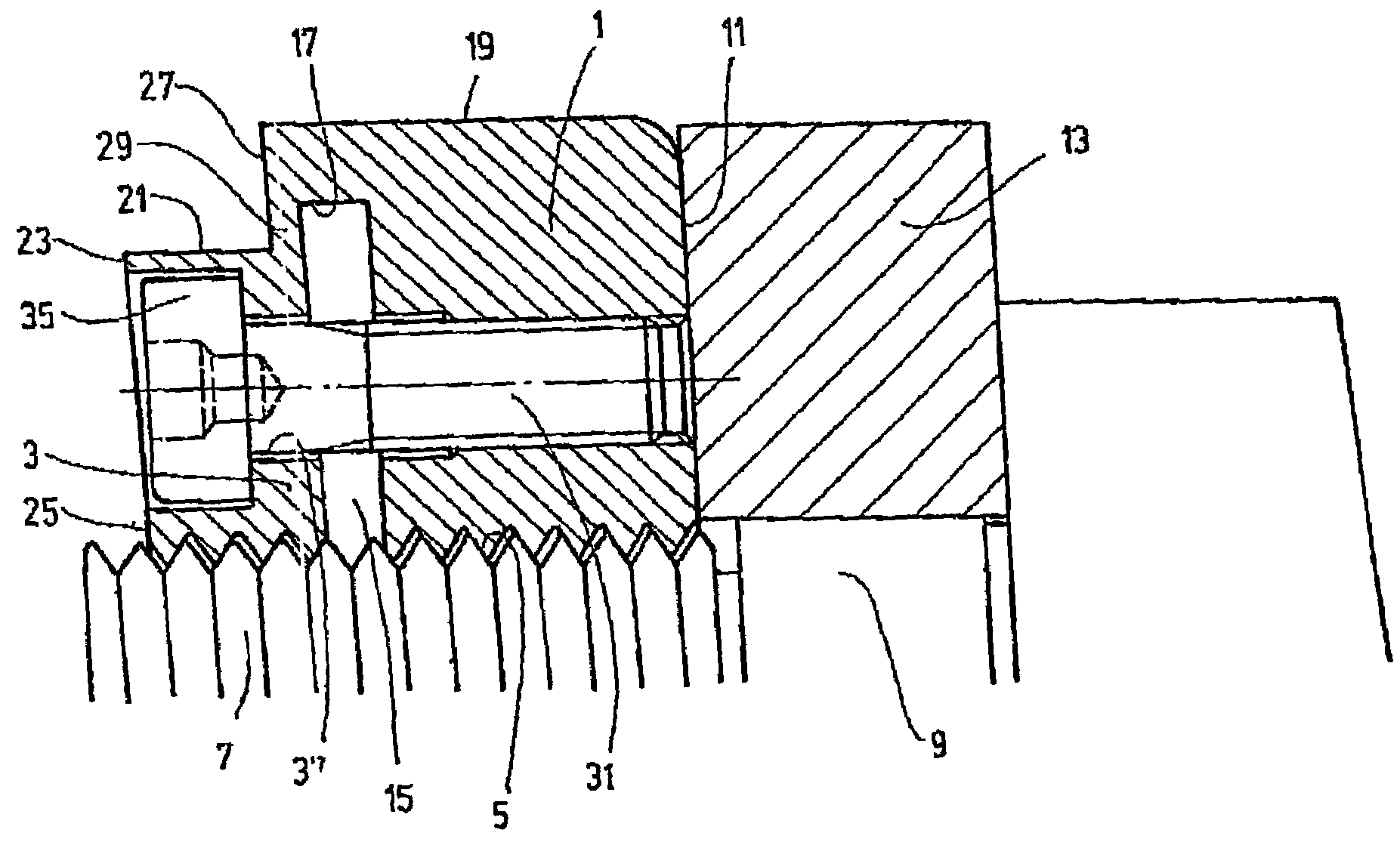
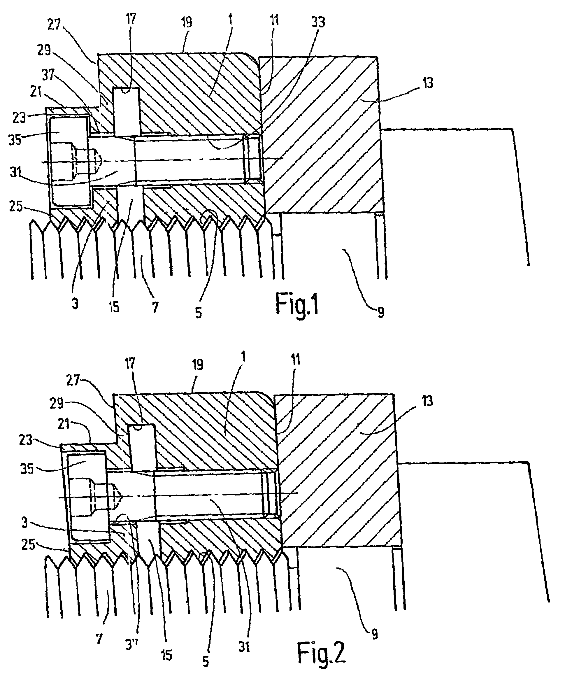
[0016]The threaded ring shown in FIG. 1 has two primary components, specifically a first body component 1 which functions as set collar or adjusting nut and a second body component 3 which forms a retaining ring. The two body components 1 and 3 are provided with continuous internal threading 5 by which they are screwed on a section of a spindle 9 provided with external threading 7. The body component 1 has on the end a planar surface 11 functioning as contact surface for fixing the position of an annular component 13 seated on the spindle 9 as shaft collar.

[0017]Between the two body components 1 and 3, a gap 15 extends in the radial direction from the internal threading. A radially outer end 17 of the gap is spaced at a radial distance from the circumference or circumferential area 19 of the first body component 1. The second body component 3 has a circumferential area 21 with a smaller external diameter than the external circumference 19 of the first body component 1. This circumfe...


PUM


Abstract

A threaded ring has a single-piece body provided with an internal screw thread and two parts (1 and 3). The first part forms an adjusting ring having an end face (11) located in a radial plane. The second part (3) forms a retaining ring connected to the first part (1) of the body by an elastically flexible wall part (29) of the body forming a gap (15) between the two parts of the body (1 and 3). An actuating device (31) permits the geometry of the gap (15) to be adjusted due to the elastic flexibility of the wall element (29). The second part (3) of the body, used as a retaining ring, has a peripheral region (21) for the formation of the elastically flexible wall element (29), and has a smaller outer diameter than the first part (1). The outer diameter of the peripheral region is located on a smaller radius than the radially outer end (17) of the gap (15). The outer end of the gap, in turn, is located on a smaller radius than the periphery (19) of the first part (1) of the body. The peripheral region (21) of the second part (3), with a reduced diameter, ends at an axial distance from the gap (15), defining the extension of the flexible wall element (29) in the axial direction.

Description

BACKGROUND OF THE PRESENT INVENTION[0001]The present invention relates to a threaded ring having a one-piece body provided with internal threading and two body components. One body component is in the form of a set collar with a planar surface on the end in a radial plane. The other body component forms a retaining ring connected to the first component to form a gap positioned between the two body components by an elastically flexible wall component. An actuating mechanism permits the geometry of the gap to be adjusted on the basis of the elastic flexibility of the wall componentBACKGROUND OF THE INVENTION[0002]Threaded rings of this type are disclosed in DE Patent Application 1 675 685, for example, are commercially available, and are applied in various areas of mechanical engineering. The body component forming the planar face serves as a high-precision nut seated on the external threading of a shaft or spindle. The axial position of the nut may be determined with high accuracy by...

Claims


Application Information

Patent Timeline
IPC IPC(8): F16B39/02
CPCF16B39/028
Inventor METZGER, HEINZ
Owner SPIETH MASCHENELEMENTE
Why Eureka
Try Eureka