Dual-sectioned grounding bushing assembly

a bushing assembly and dual-section technology, applied in the direction of connection contact member materials, coupling device connections, manufacturing tools, etc., can solve the problems of increased costs for contractors and consumers alike, unsatisfactory conditions, and laboriousness

Active Publication Date: 2007-02-27
BRIDGEPORT FITTINGS LLC
View PDF21 Cites 54 Cited by
  • Summary
  • Abstract
  • Description
  • Claims
  • Application Information

AI Technical Summary

Benefits of technology

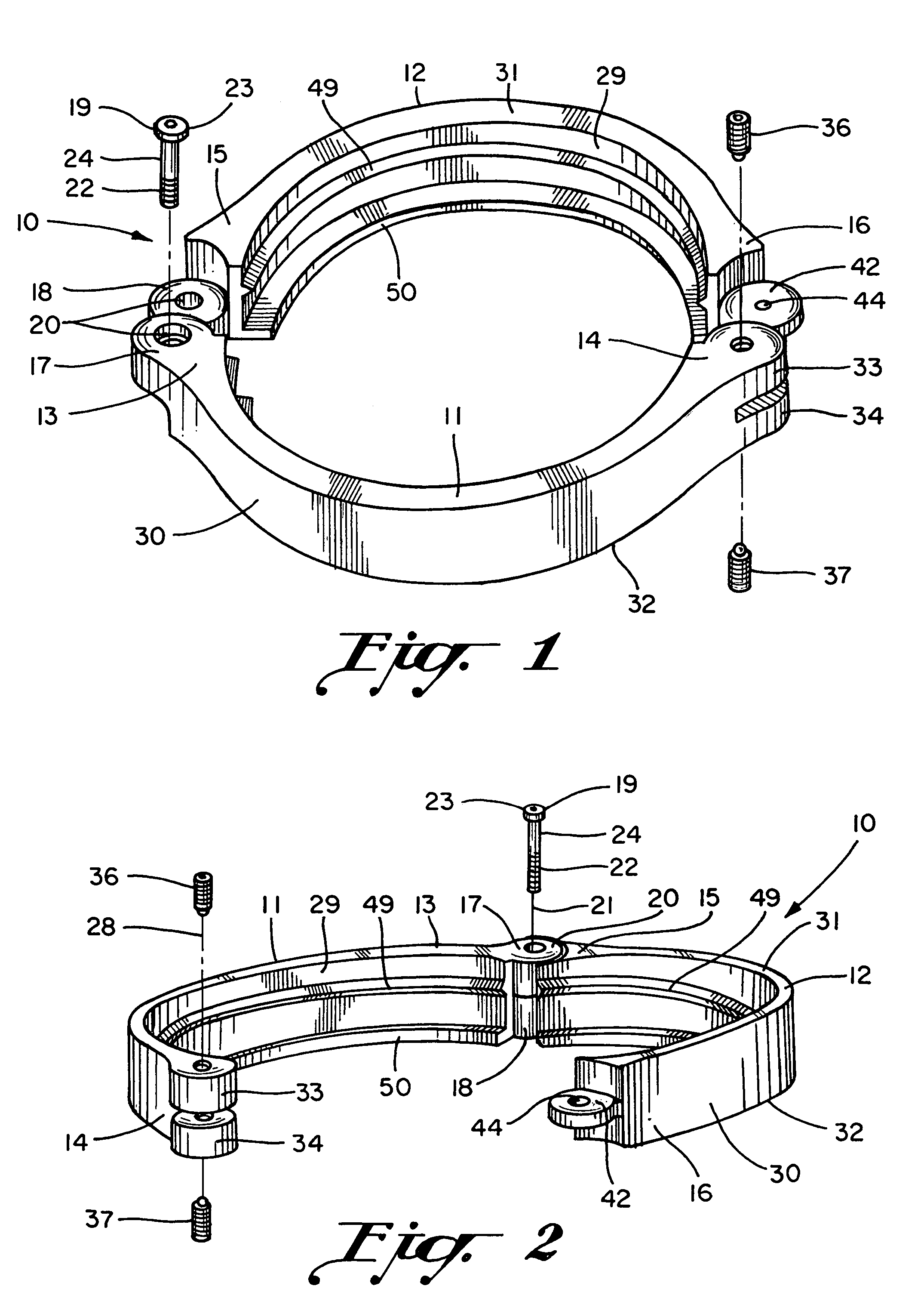
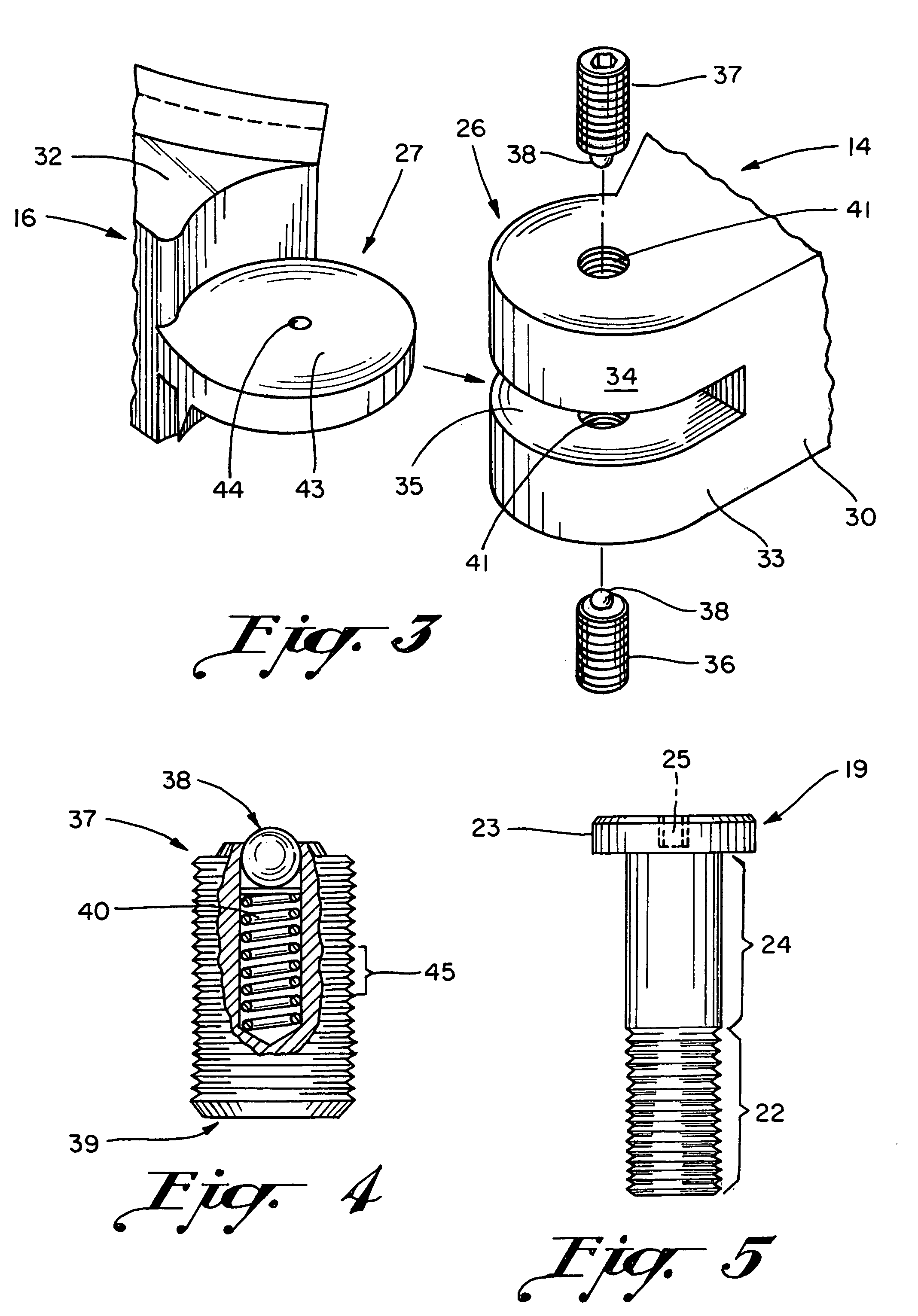
[0019]The triaxial pivot means may be defined by first section pivot structure and second section pivot structure. The first section pivot structure is integrally formed with the first bushing section adjacent the first section pivot end and the second section pivot structure is integrally formed with the second bushing section adjacent the second section pivot end. The first and second section pivot structures are cooperatively associated with one another for movably connecting the first bushing section to the second bushing section. The triaxial pivot means thus allow triaxial movement between the first bushing section and the second bushing section.
[0023]The latch-pin knuckle latch means may be defined by first section latch knuckle structure, second section latch knuckle structure, and a latch pin. The first section latch knuckle structure is integrally formed with the first bushing section adjacent the first section latch end and the second section latch knuckle structure is integrally formed with the second bushing section adjacent the second section latch end. The first and second latch knuckle structures each comprise latch pin-receiving structure, which structure has a latch pin axis. The latch pin is insertable into the latch pin-receiving structure for removably fastening the first section latch end to the second section latch end. The latch pin axis is substantially parallel to the bushing axis.

Problems solved by technology

In other words, without a properly installed bushing in place, the electrical conductors may become damaged, leading to unsafe conditions.
The described methodological error significantly increases the labor involved at a given job site, thus increasing costs to contractors and consumers alike.
Methodological errors such as those here identified are difficult to completely eradicate given the occasional human error.
It will thus be noted that while the '469 Patent does teach a hinged bushing, which bushing enables an installer to install the device either before or after electrical connections are finalized, the '469 Patent does not teach a hinged grounding bushing.
The '469 Patent does not address the structural peculiarities inherent in essential grounding bushing art.
Further, while the '411 Patent does disclose a hinged ground clamp, it does not teach a hinged grounding bushing.
From a review of the above-referenced patents and other prior art generally known to exist, it will be seen that the prior art does not teach a dual-sectioned grounding bushing for enabling installers to install the bushing either before or after electrical connections are finalized at a junction box.

Method used


Image

  • Dual-sectioned grounding bushing assembly
  • Dual-sectioned grounding bushing assembly
  • Dual-sectioned grounding bushing assembly

Examples


embodiment no.1

Alternative Embodiment No. 1

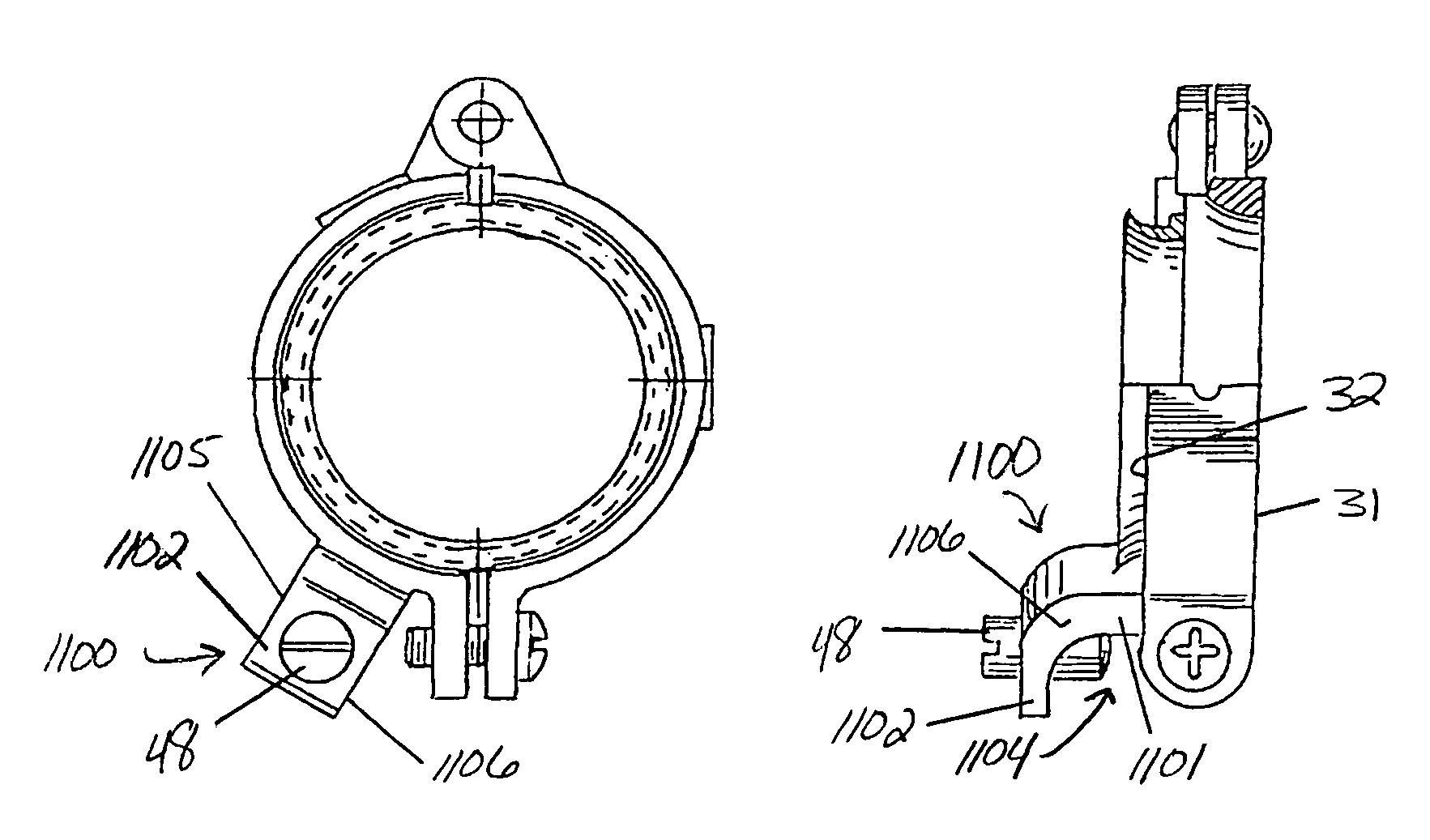
[0091]A first alternative embodiment of the present invention also concerns a dual-sectioned grounding bushing assembly, which grounding bushing assembly is illustrated and referenced at 100 in FIGS. 7 and 12. Grounding bushing assembly 100 is substantially similar to grounding bushing assembly 10 save for certain structural differences as embodied in the latch means and inner annular surface 29.

[0092]From an inspection of FIGS. 7 and 12 it will be noted that the latch means of grounding bushing assembly 100 differs from the latch means of grounding bushing assembly 10 in several key respects. The latch means of grounding bushing assembly 100 may be described by the following specifications.

[0093]The latch means of grounding bushing assembly 100 preferably comprises first section latch structure 126 as illustrated and referenced in FIGS. 7, 12–14, 16, and 17(b); second section latch structure 127 as illustrated and referenced in FIGS. 7, 12–14, 16, 17(a),...

embodiment no.2

Alternative Embodiment No. 2

[0098]A second alternative embodiment of the present invention concerns a grounding bushing assembly 200 as illustrated and referenced in FIGS. 8 and 9. Grounding bushing assembly 200 is substantially identical to grounding bushing assembly 100 save for certain features as identified in the latch means. In this regard, it will be seen that the latch means of grounding bushing assembly 200 preferably comprises first section latch structure 226, second section latch structure 227, and at least one latch pin 236 all as illustrated and referenced in FIGS. 8 and 9. It will be seen from an inspection of the noted drawing figures that first section latch structure 226 is preferably integrally formed with first bushing section 11 adjacent first section latch end 14 and that second section latch structure 227 is preferably integrally formed with second bushing section 12 adjacent second section latch end 16. First section latch structure 226 and second section lat...

embodiment no.3

Alternative Embodiment No. 3

[0100]A third alternative embodiment of the present invention concerns a grounding bushing assembly 300 as has been generally illustrated and referenced in FIG. 10. Grounding bushing assembly 300 is substantially identical to grounding bushing assembly 100 and grounding bushing assembly 200 save for certain features as identified in the latch means. In this regard, it will be seen that the latch means of grounding bushing assembly 300 preferably comprises first section latch structure 326, second section latch structure 327, and at least one latch pin 336 all as illustrated and referenced in FIGS. 10 and 22.

[0101]It will be seen from an inspection of the noted drawing figure that first section latch structure 326 is preferably integrally formed with first bushing section 11 adjacent first section latch end 14 and that second section latch structure 327 is preferably integrally formed with second bushing section 12 adjacent second section latch end 16. Fir...


PUM


Abstract

The present invention provides a grounding bushing assembly essentially comprising a first bushing section, a second bushing section, select pivot structure, select latch structure, and select ground conductor attachment structure. The first bushing section, second bushing section, select pivot structure, select latch structure, and select ground conductor attachment structure are all preferably constructed from electrically conductive materials for allowing electric charges to migrate through the material. The first and second sections each comprise an arc length intermediate the section ends, which are lengths together function to cooperatively form an annular, dual-sectioned, grounding bushing. The resulting grounding bushing comprises an inner annular surface, an outer annular surface, a conductor inlet end, a conductor outlet end, and unique ground conductor attachment structure. The present invention enables an installer thereof to install the same in cooperative association with a ground conductor either before or after electrical connections are finalized.

Description

PRIOR HISTORY[0001]This application is a continuation-in-part patent application claiming priority to U.S. patent application Ser. No. 10 / 789,752, filed in the United States Patent and Trademark Office on Feb. 26, 2004 now U.S. Pat. No. 6,840,782.BACKGROUND OF THE INVENTION[0002]1. Field of the Invention[0003]The present invention generally relates to an improved bushing assembly for use in combination with electrical conduit. More particularly, the present invention relates to a bifurcated or dual-sectioned grounding bushing assembly, which grounding bushing assembly effectively allows electricians to install the grounding bushing assembly either before or after completing wiring connections at a junction box.[0004]2. Description of the Prior Art[0005]Bushings are typically installed on the terminal end of electrical conduit at an electrical junction box to serve as an aperture lining through which electrical conductors pass. Bushings are often required so as to reduce the likeliho...

Claims


Application Information

Patent Timeline
Patent Type & Authority Patents(United States)
IPC IPC(8): H01R13/648E05D11/00H01R4/64
CPCH01R4/643Y10T16/537
Inventor BORDEN, AARON M.ZANZOLA, TOMAS J.
Owner BRIDGEPORT FITTINGS LLC
Why Eureka
Try Eureka