Electrical contact with elastic return and electrical connection element equipped with the same

a technology of electrical contact and elastic return, which is applied in the direction of coupling contact members, multi-conductor cable end pieces, coupling device connections, etc., can solve the problems of additional resistance and the inability to perform elastic movement along the general longitudinal axis of the conductor, so as to reduce the size of the contact and eliminate and reduce certain amounts of electrical resistance

Inactive Publication Date: 2007-02-27
MARECHAL ELECTRIC
View PDF19 Cites 11 Cited by
  • Summary
  • Abstract
  • Description
  • Claims
  • Application Information

AI Technical Summary

Benefits of technology

[0010]The invention provides a simple electrical contact with elastic return making it possible in particular to establish a connection with end-on contact pressure for a variety of applications as described below. In addition, the invention makes it possible in particular to reduce the size of the contact and to eliminate and reduce certain amounts of electrical resistance.
[0012]In an embodiment, the conductive part is cylindrical, and the flexible blade is in the form of a circular or elliptical segment or zone, in which case, for a contact including a single blade and a single cut, the depth of the cut is greater than the radius of the cylindrical part. By way of optional example, the cut in the conductive part lies in a plane perpendicular to the longitudinal axis of said part. Preferably, the width of the cut is no greater than the maximum acceptable deflection for the flexible blade prior to reaching its elastic limit, which maximum deflection is a function of the nature of the materials used and the depth of the cut, so that the blade cannot exceed its elastic limit.
[0014]Preferably, the flexible blade is also provided over at least a portion of its surface with a pellet of silver for improving the passage of electric current between said contact and the opposing electrical contact.
[0024]Moreover, a material can be provided over at least a portion of the at least one flexible blade to improve passage of electric current between the contact and the opposing electrical contact.

Problems solved by technology

In addition to the problems inherent to repeatedly deforming the deformable conductor, those known contacts are of significant length, and they lead to additional resistance due to the crimping zones between the various parts.
Nevertheless, under those circumstances, the elastic movement cannot be performed along the general longitudinal axis of the conductor.

Method used


Image

  • Electrical contact with elastic return and electrical connection element equipped with the same
  • Electrical contact with elastic return and electrical connection element equipped with the same
  • Electrical contact with elastic return and electrical connection element equipped with the same

Examples


Embodiment Construction

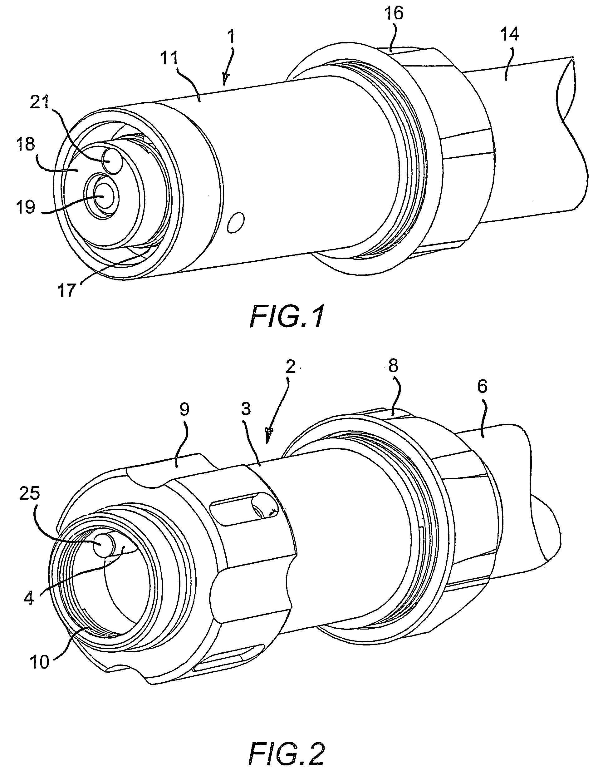
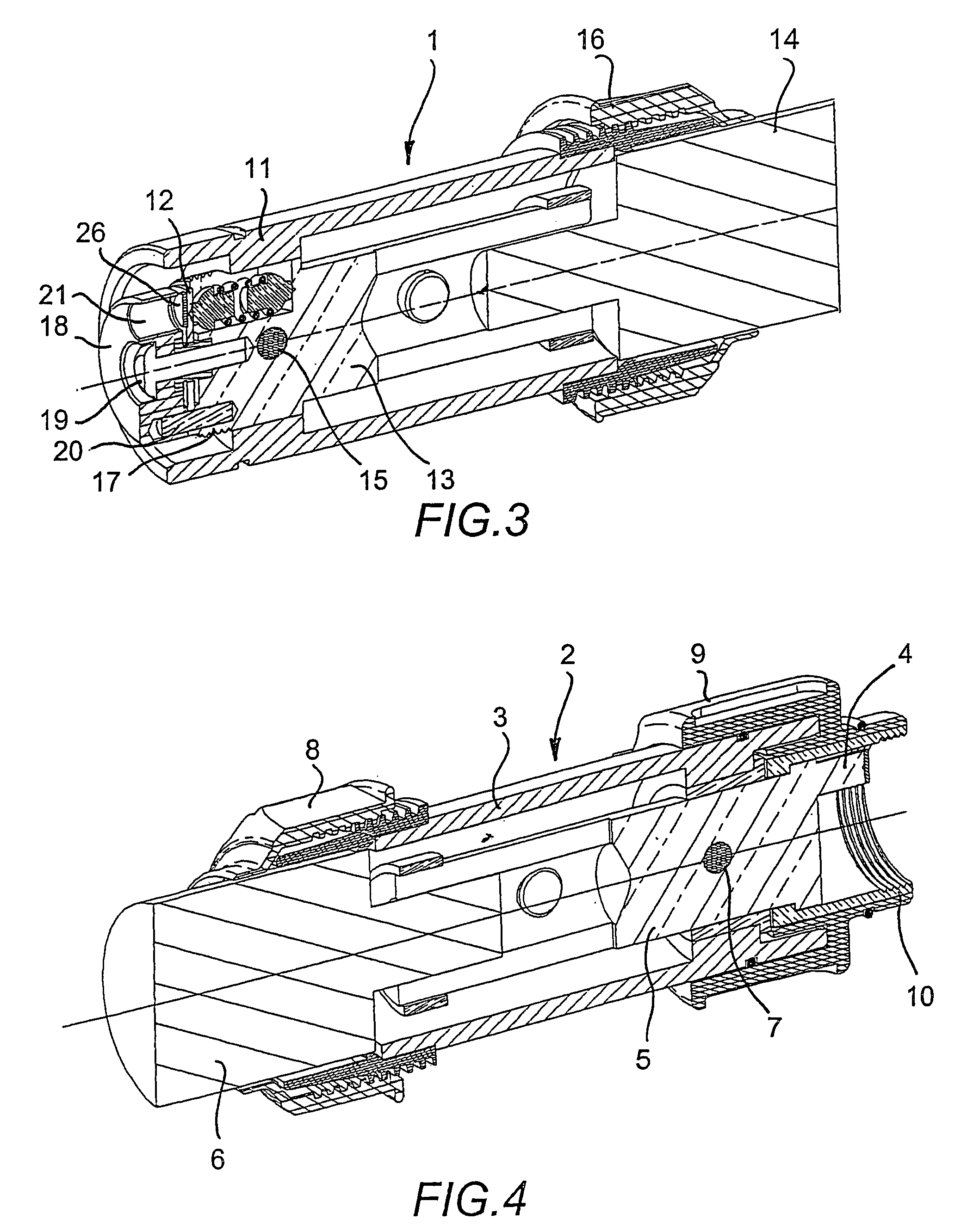
[0039]In the drawings, there can be seen by way of example a single-pole cable coupler made up of a connector 1 and a plug 2 (FIGS. 1 to 5).

[0040]Plug 2 is designed to couple with connector 1 by taking up the connection position shown in section in FIG. 5.

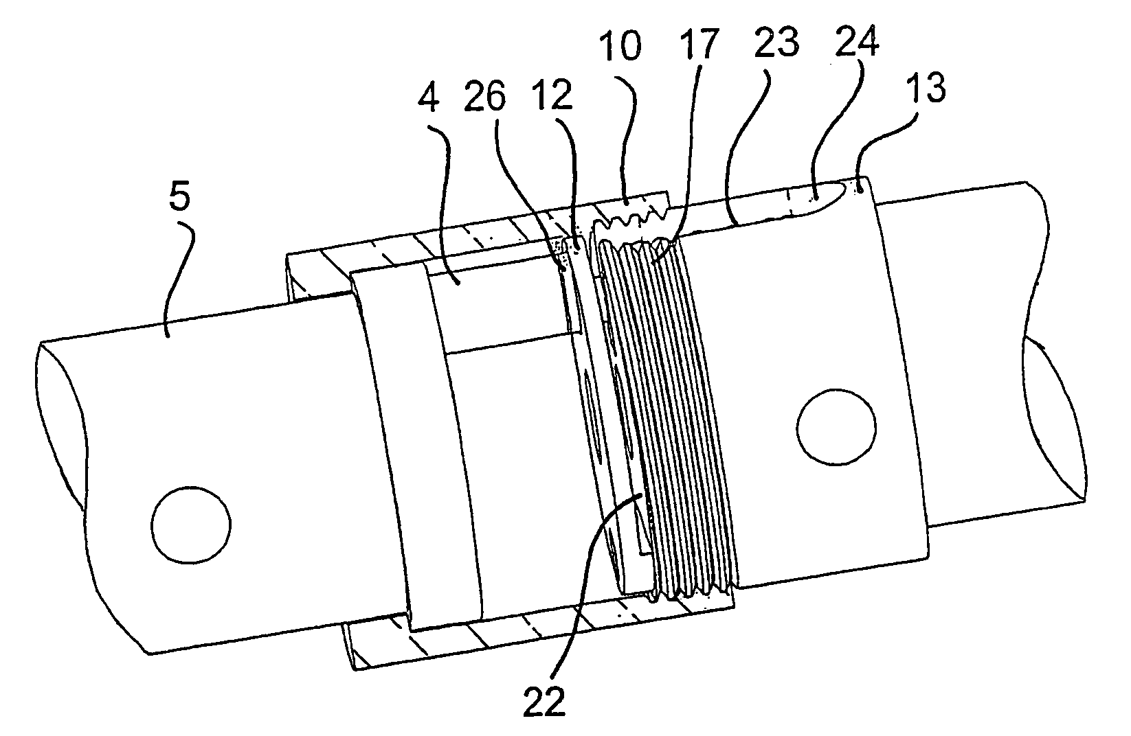
[0041]Plug 2 comprises an insulating case 3 in which there is arranged a contact pin 4 (FIGS. 2, 4, 5, 6, and 7) secured to a cylindrical metal part 5, itself connected to a cable 6 by screw fastening, crimping, or other engagement. By way of example, part 5 is held in case 3 by a dowel 7 (FIGS. 4 and 5).

[0042]In the embodiment shown, pin 4 is off-center, but it could be less off-center or not off-center at all depending on its nature and / or the disposition of the contact of the connector described below.

[0043]In this case, cable 6 is also held by a cable clamp 8, while a clamping ring 9 is provided to turn a partially-tapped screw ring 10, described in greater detail below, and serving, when actuated, to lock the coupling between ...


PUM


Abstract

Electrical contact with elastic return and process for forming electrical contact with elastic return. Electrical contact includes a conductive part having a front surface structured and arranged to face an open end. The conductive part has a cut arranged to form at least one flexible blade from the front surface of a conductive part. The instant abstract is neither intended to define the invention disclosed in this specification nor intended to limit the scope of the invention in any way.

Description

CROSS-REFERENCE TO RELATED APPLICATIONS[0001]The present application is a Continuation of International Patent Application No. PCT / FR2003 / 003582 filed Dec. 4, 2003, and claims priority of French Patent Application No. 02 / 15435 filed Dec. 6, 2002. Moreover, the disclosure of International Patent Application No. PCT / FR2003 / 003582 is expressly incorporated by reference herein in its entirety.BACKGROUND OF THE INVENTION[0002]1. Field of the Invention[0003]The invention relates to an electrical contact with elastic return and to an electrical connection element provided with at least one such contact.[0004]2. Discussion of Background Information[0005]Electrical contacts with elastic return, in particular for end-on contact pressure, are well known.[0006]In one embodiment, they comprise a contact head which comes into elastic engagement with an opposing contact under the action of a helical spring that surrounds a deformable conductor such as a braid, which conductor is connected to a cab...

Claims


Application Information

Patent Timeline
Patent Type & Authority Patents(United States)
IPC IPC(8): H01R29/00H01R11/11H01R13/187H01R13/207H01R13/24H01R13/512H01R13/59H01R13/622H01R43/20
CPCH01R13/2421H01R24/20H01R43/20H01R13/187H01R13/512H01R2101/00H01R13/622H01R13/59
Inventor CRESTIN, JOSEPH
Owner MARECHAL ELECTRIC
Why Eureka
Try Eureka