
Wound closure device

a technology of wound closure and wire/needle, which is applied in the field of wound closure devices, can solve the problems of cell explosion, wire/needle becoming very hot, and intense electrical sparks rapidly heating tissue,

Inactive Publication Date: 2007-02-27
INSTRASURGICAL
View PDF15 Cites 1191 Cited by
  • Summary
  • Abstract
  • Description
  • Claims
  • Application Information

AI Technical Summary

Benefits of technology

"The present invention relates to a wound closure device and method for managing wounds in the body, particularly in the arteries and veins. The device includes a handle, body portion, and stapling mechanism for deploying a fastener into body tissue. The device can be used in various procedures such as cardiac and soft-tissue procedures, and can also be used to close wounds in the brain, heart, and lungs. The device can be used with a vascular introducer for expanding the wound site and can also be used with a guidewire for positioning the device. The method involves inserting a guidewire into the vessel, placing a vascular introducer with a dilator over the guidewire, and using the stapler to close the wound. The invention provides a wound closure device that can be easily used and can effectively manage wounds in the body."

Problems solved by technology

Moreover, during electrocautery, current does not enter the patient's body, but flows though a wire or needle associated with the instrument and due to their impedance the wire / needle become very hot.
Such a waveform creates short, intense electrical sparks to rapidly heat tissue; cells are exploded and the heat dissipated as steam.
A disadvantage of the wound site management systems disclosed in U.S. Pat. Nos. 6,755,842 and 6,506,210 and other prior art devices and systems is that they do not include an integrated cauterizing mechanism.
This not only adds complexity to the surgical procedure, but increases the time required for hemostasis.

Method used


Image

  • Wound closure device
  • Wound closure device
  • Wound closure device

Examples


Embodiment Construction

[0034]Reference is now made to the accompanying figures for the purpose of describing, in detail, preferred and exemplary embodiments of the present disclosure. The figures and accompanying detailed description are provided to describe and illustrate exemplary manners in which the disclosed subject matter may be made and used, and are not intended to limit the scope thereof.

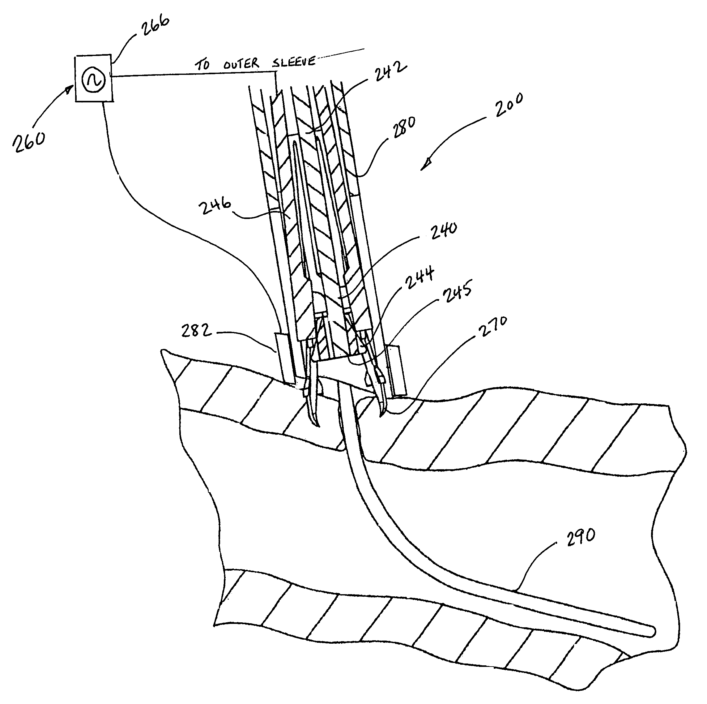
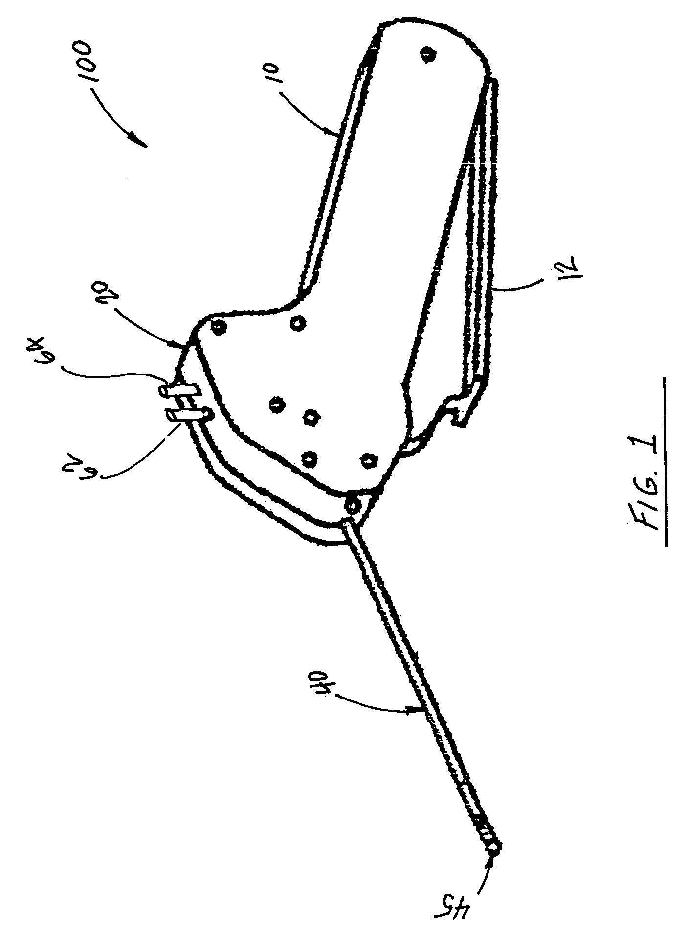
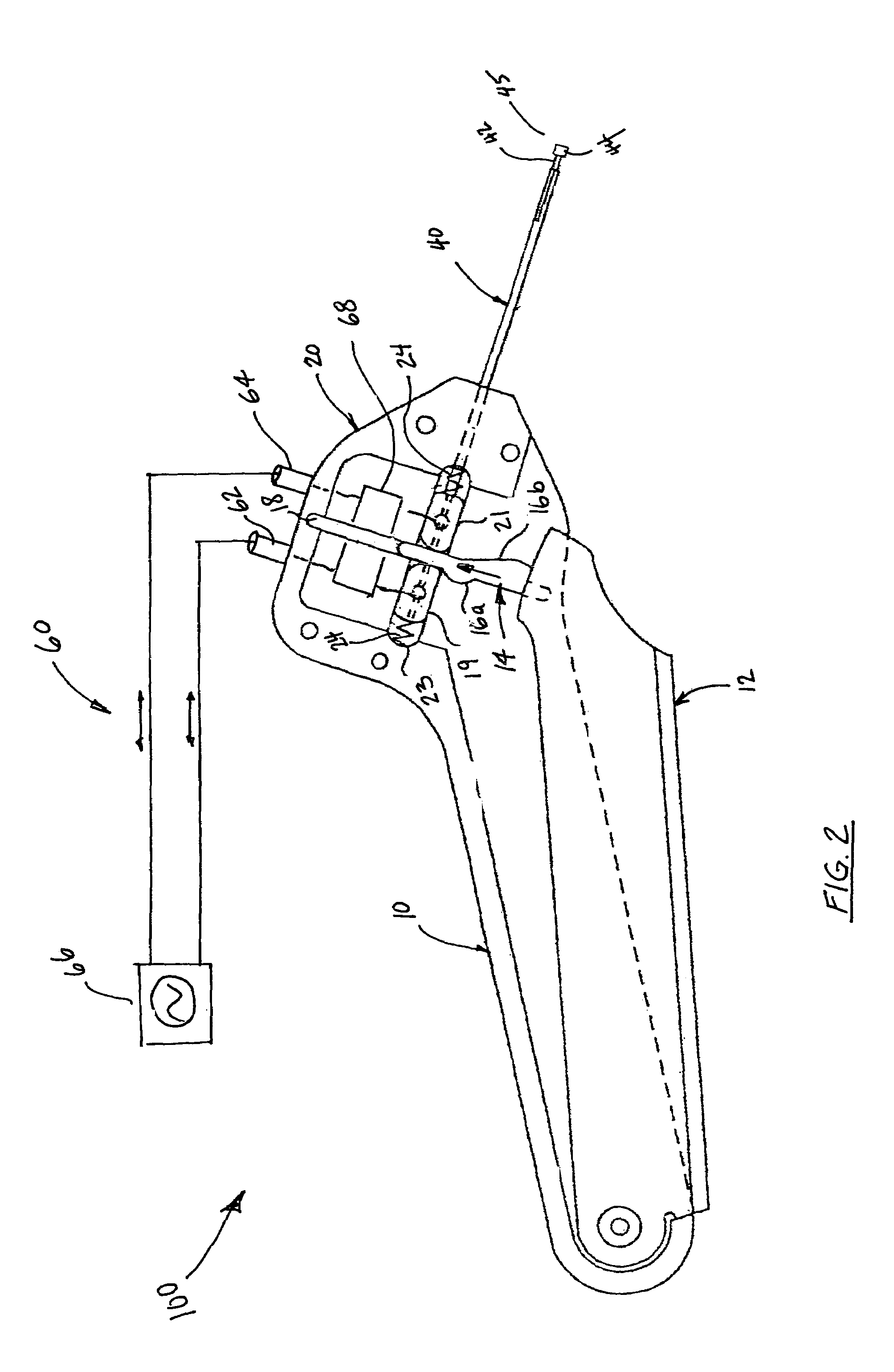
[0035]Referring now to FIG. 1, there is illustrated a wound closure device constructed in accordance with an embodiment of the present invention and designated generally by reference number 100. Closure device 100 includes a handle 10, a main body section 20 posited at the distal end of the handle 10 and a stapling mechanism 40 extending distally from the main body section 20. The distal tip 45 of the stapling mechanism 40 is adapted for holding, forming and deploying a staple 70 (FIG. 3). An actuator mechanism 12 is associated with the handle portion 10 of the closure device 100 and causes the staple 70, or at l...


PUM


Abstract

Disclosed is a wound closure device and method for using the same. The wound closure device includes a handle, a body portion extending distally from the handle, a stapling mechanism extending distally from the body portion and a mechanism for supplying electrical energy from an RF power supply to a fastener (e.g. staple) which is associated with the stapling mechanism. In a representative embodiment, the stapling mechanism includes an inner rod member disposed within an elongated outer sleeve and slidably movable therein. The rod member has an enlarged tip for deploying the fastener that is supported adjacent to the tip into body tissue. The wound closure device further includes an actuator mechanism associated with the handle and body portion and configured to facilitate relative movement of the inner rod and the outer sleeve so as to deploy the fastener into body tissue. In alternative embodiments, a second pole of the RF power supply is connected to a conductive ring associated with a vascular introducer.

Description

BACKGROUND OF THE INVENTION[0001]1. Field of the Invention[0002]The present invention relates to wound closure devices for use during and after invasive medical procedures, and more particularly to, electrosurgical devices that include a stapler for closing a wound and an integrated mechanism which applies electrical energy to the body tissue within which the wound is formed to cauterize the wound site.[0003]2. Background of the Related Art[0004]The application of electrical energy to a surgical site for the purpose of cutting or cauterizing body tissue has been known for some time in the medical community and is generally referred to as either electrocautery and electrosurgery. Often “electrocautery” is used to describe “electrosurgery,” but this is incorrect.[0005]Electrocautery refers to applications wherein the electrical energy is supplied in a direct current, i.e., electrons flowing in one direction. In contrast, in electrosurgery an alternating current energy supply is used. ...

Claims


Application Information

Patent Timeline
Patent Type & Authority Patents(United States)
IPC IPC(8): A61B18/14
CPCA61B17/0057A61B17/0644A61B17/068A61B18/14A61B2018/0063A61B2017/00668A61B2017/0641A61B2017/2913A61B2017/292A61B2017/00637
Inventor NARDELLA, PAUL C.
Owner INSTRASURGICAL
Learn More