Bone fixation system

a technology of fixation system and bone, which is applied in the field of bone fixation system, can solve the problems of high death rate, frequent complications, and misalignment, and achieve the effect of preventing the rotation of the second implant and preventing the sliding of the second implan

Inactive Publication Date: 2007-02-27
SYNTHES USA
View PDF63 Cites 57 Cited by
  • Summary
  • Abstract
  • Description
  • Claims
  • Application Information

AI Technical Summary

Benefits of technology

[0011]The present invention is also directed to a coupling mechanism for coupling a first fracture fixation implant to a second fracture fixation implant. The coupling mechanism includes a body member receivable in the first implant and including a single prong extending from the body for contacting a surface of the second implant. The coupling mechanism further includes a drive member rotatably coupled to the body member for threadable engagement with the first implant. The drive member rotates freely with respect to the body member and may be used to urge the body member toward the second implant such that the single prong contacts the surface of the second implant and substantially prevents rotation of the second implant with respect to the first implant. More specifically, the single prong may define a first engagement surface, the second implant may define a second engagement surface, and the first and second engagement surfaces may interact to substantially prevent rotation of the second implant with respect to the first implant.
[0012]According to a further aspect of the invention, the single prong may limit sliding of the second implant with respect to the first implant. For example, the second engagement surface may include stops formed adjacent at least one of its ends for contacting the prong to prevent further sliding of the second implant.

Problems solved by technology

A high incidence of death is associated with hip fractures due to the injury itself or related complications.
Frequent complications may arise when two or more bone fragments are forced towards each other when the patient supports his or her weight on the healing bone.
The prior art blades, however, may be susceptible to migration within the bone fragment and, even worse, may break free or pull out of the bone fragments, thus allowing the bone fragments to separate and / or become misaligned.
Prior art blades are also susceptible to bending stresses, which may lead to undesirable bending or breakage of the blade.
In addition, many prior art coupling mechanisms provide unlimited amounts of sliding between the blade and the side plate or intramedullary nail, which may lead to disassembly of the blade and side plate / intramedullary nail.
Furthermore, prior art coupling mechanism are often complicated and difficult to assemble during implantation.

Method used


Image

  • Bone fixation system
  • Bone fixation system
  • Bone fixation system

Examples


Embodiment Construction

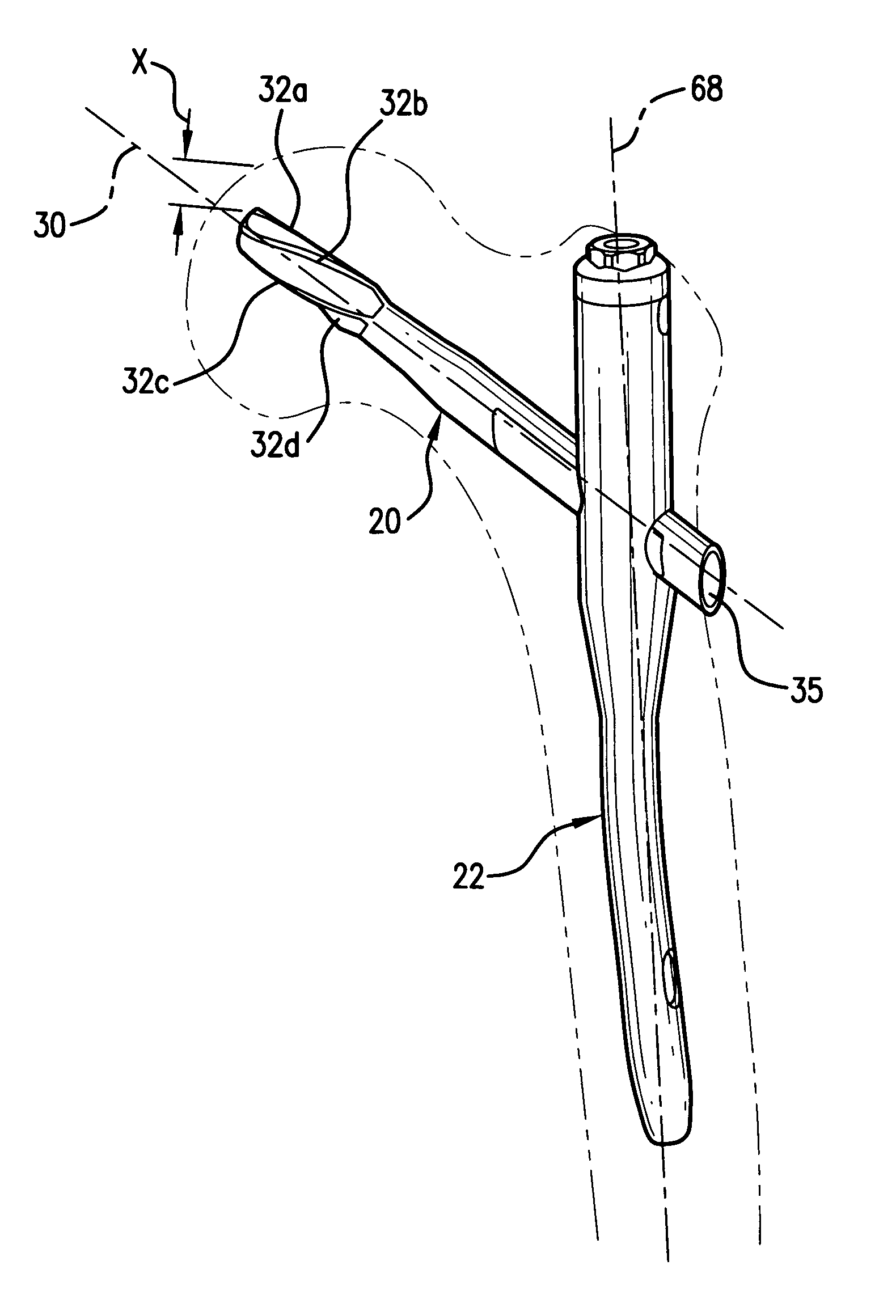
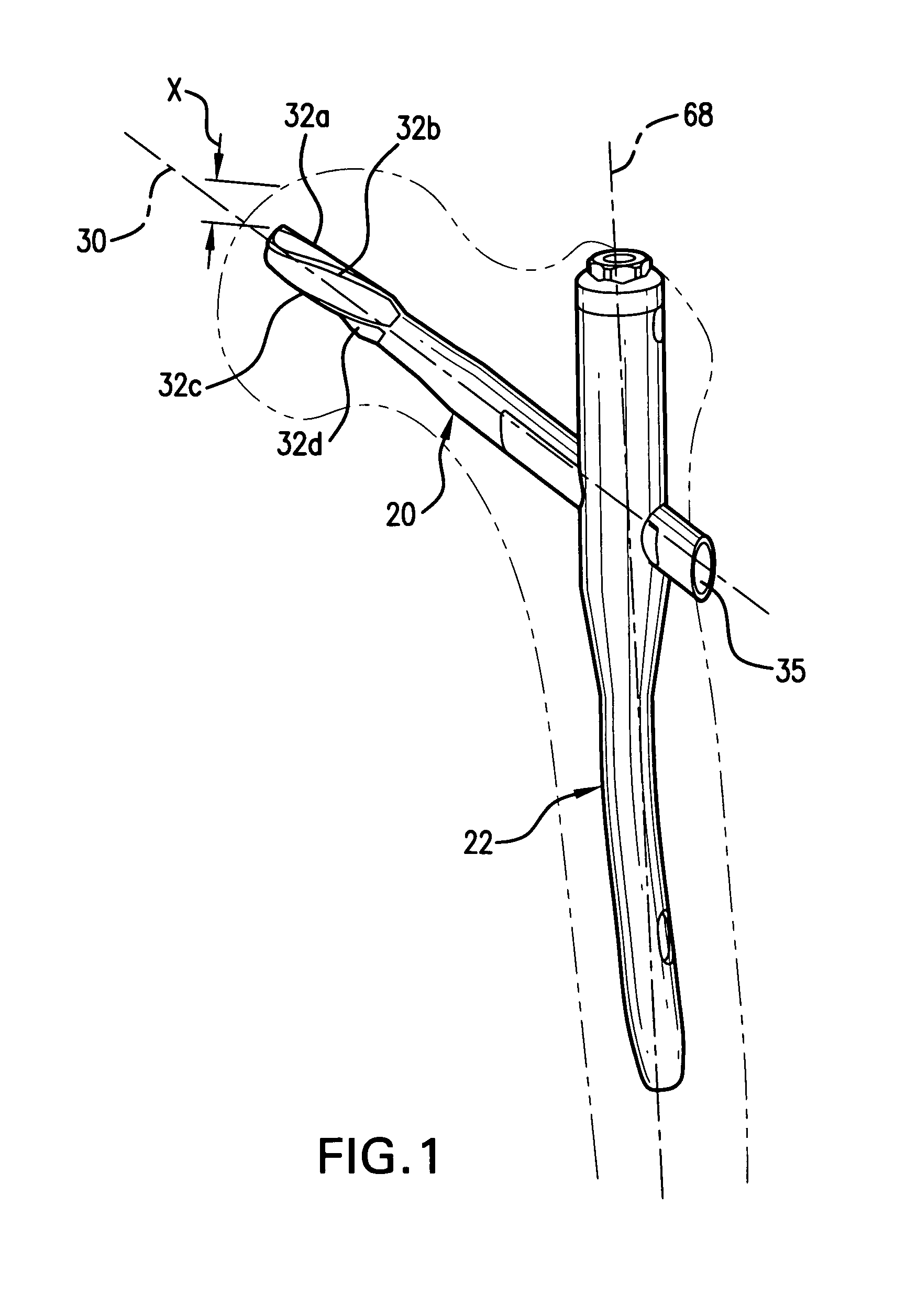
[0035]Referring to FIG. 1, a fracture fixation implant 20 according to one embodiment of the present invention is shown implanted in a femur and coupled to a second fracture fixation implant 22, which is shown for illustrative purposes as an intramedullary nail 22. Implant 20 may be used in conjunction with an intramedullary nail 22 or other fracture fixation member to treat orthopaedic trauma, impending bone fractures, and bone fractures. For example, implant 20 may be used to treat intertrochanteric fractures of the femur. Implant 20 is not limited to use in conjunction with an intramedullary nail 22, however, and may be used alone or in conjunction with any number of implants, bone plates, etc., known to one of ordinary skill in the art. Furthermore, the present invention is not limited to treatment of the femur, and may be used to treat any of the bones in the human and / or animal bodies.

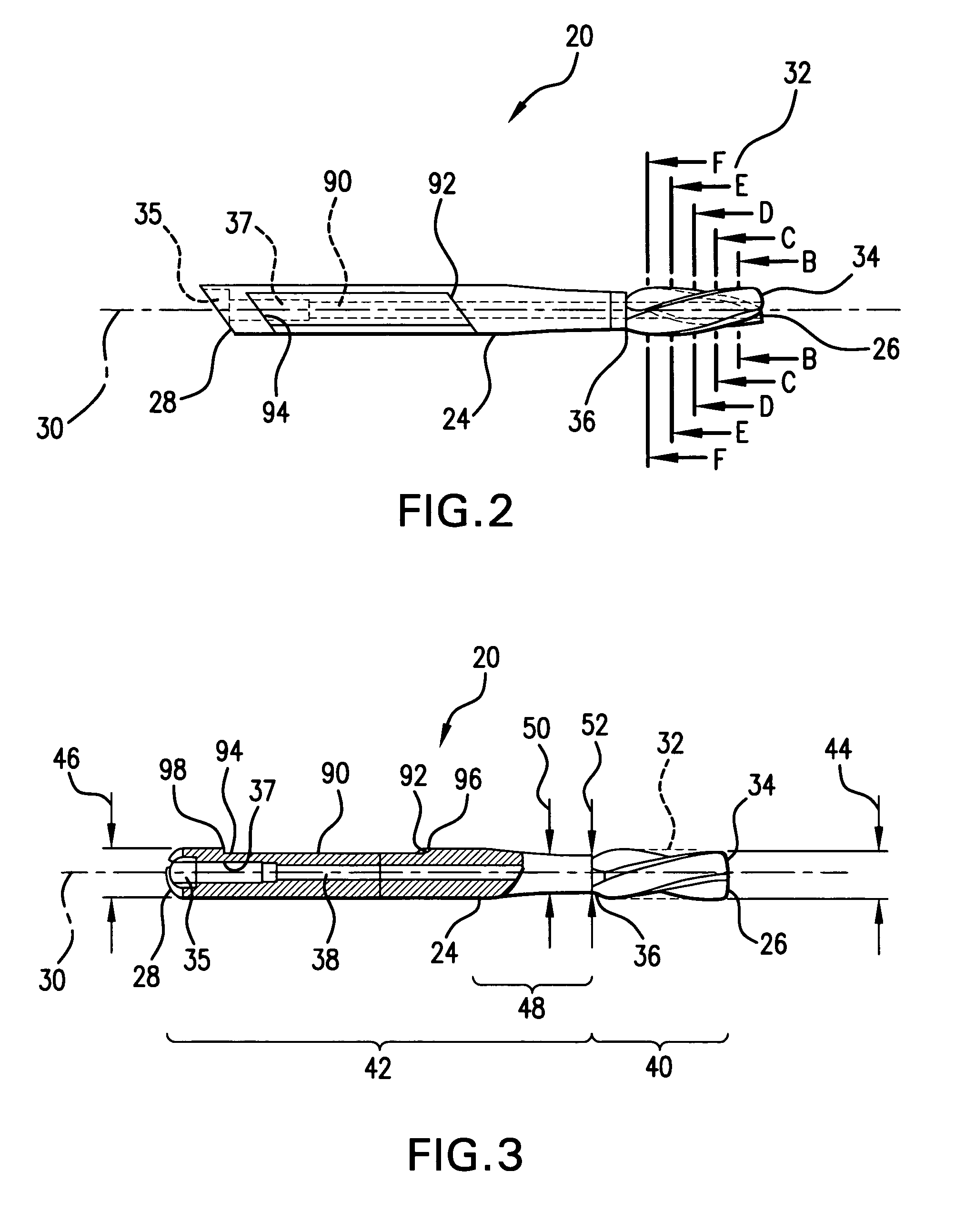
[0036]Referring to FIGS. 2 and 3, implant 20 includes a shaft 24 having a proximal end 26 and...


PUM


Abstract

An implant for fixation of a bone includes a shaft having a proximal end and a distal end, and a longitudinal axis defined between the proximal end and the distal end. A plurality of blades are disposed on the shaft, and are helically twisted about the longitudinal axis. At least one of the blades has a variable blade width that increases in a direction along the longitudinal axis. A mechanism for coupling the implant to a second fracture fixation implant may be provided separately or in combination.

Description

CROSS-REFERENCE TO RELATED APPLICATIONS[0001]The present application is a divisional of U.S. application Ser. No. 09 / 978,002, filed Oct. 17, 2001 now U.S. Pat. No. 6,835,197.FIELD OF THE INVENTION[0002]The present invention relates generally to a system for fixation of two or more parts of a fractured bone. More specifically, the present invention relates to a bone implant and locking apparatus for internal fixation of a long bone, such as a femur.BACKGROUND OF THE INVENTION[0003]Fractures commonly occur in the femur, and especially in the femoral neck and intertrochanteric regions. Traditionally, these fractures have been treated using a nail located in the femoral head in cooperation with a side plate located on the outside of the femur, or in cooperation with an intramedullary nail located in the intramedullary canal. The nail cooperates with the side plate or intramedullary nail to align and compress the bone fragments.[0004]A high incidence of death is associated with hip fract...

Claims


Application Information

Patent Timeline
Patent Type & Authority Patents(United States)
IPC IPC(8): A61B17/58A61B17/17A61B17/74A61B17/78A61B17/92A61F2/28
CPCA61B17/921A61B17/744A61B17/1721A61B17/74
Inventor ROTH, CHRISTOPH ANDREASHALL, IV, HARRY T.
Owner SYNTHES USA
Why Eureka
Try Eureka