Method of synchronous serial communication and system for synchronous serial communication

a serial communication and synchronous technology, applied in the direction of generating/distributing signals, digital output to print units, instruments, etc., can solve the problems of large volume of data necessary for printing a line of color images, a comparatively long time for serial data communication, and a comparatively long time for conventional serial data communication

Inactive Publication Date: 2007-02-27
COPYER
View PDF18 Cites 7 Cited by
  • Summary
  • Abstract
  • Description
  • Claims
  • Application Information

AI Technical Summary

Problems solved by technology

However, serial data communication requires a comparatively long time if data to be transmitted are large in volume.
Because of these inconveniences, the conventional serial data communication requires a comparatively long time particularly when a data change must be added later.
If the image forming system must print a full color image, it will incorporate four printer heads, and thus data necessary for printing a line of a color image will become large in volume, and the number of clock signals will increase in association, which will unduly lengthen the time necessary for printing.
The recording method based on ink jet printing poses another problem: the amount of the ink droplet will vary depending on the temperature of the ink jet element from which the droplet is spat out.
Namely, according to the conventional serial data communication, changing of the previously sent data requires an unduly long time.

Method used


Image

  • Method of synchronous serial communication and system for synchronous serial communication
  • Method of synchronous serial communication and system for synchronous serial communication
  • Method of synchronous serial communication and system for synchronous serial communication

Examples


1st embodiment

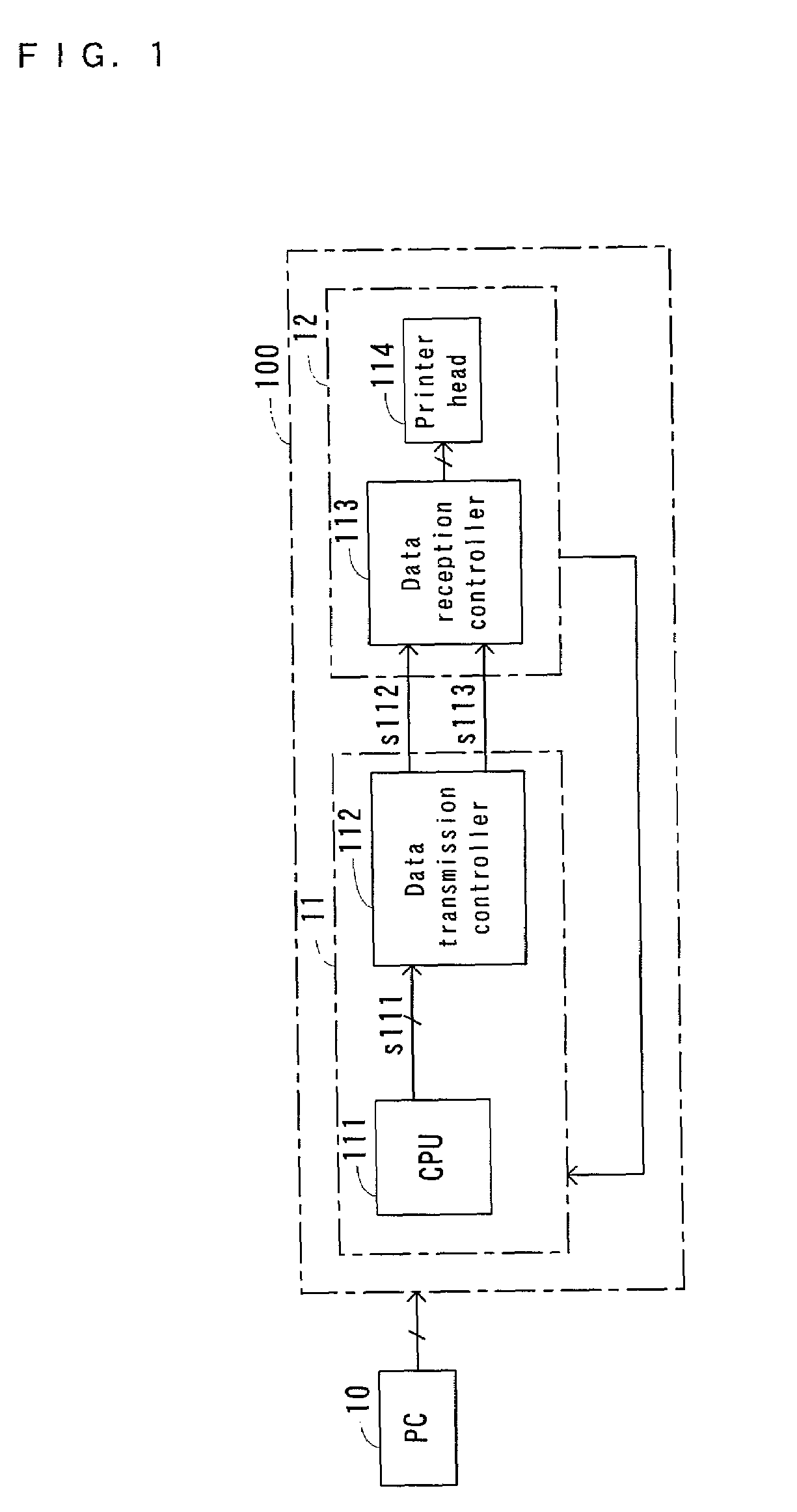
[0027][Constitution] A first embodiment of this invention will be described below with reference to attached figures. FIG. 1 is a schematic diagram to indicate the outline of an image forming system based on thermal ink jet printing representing a first embodiment of this invention. The image forming system 100 based on thermal ink jet printing shown in FIG. 1 comprises an engine portion 11 including a CPU 111 and a data transmission controller 112, and a recording head portion 12 including a data reception controller 113 and a printer head 114. Data transmission controller 112 is connected through a bus to CPU 111, and writes data in response to an instruction from CPU 111, or receives an instruction from CPU 111 for starting communication. Data transmission controller 112, on receipt of an instruction from CPU 111 for starting communication, determines which mode out of the communication modes described below will be most suitable for transmitting the data in a shortest possible t...

2nd embodiment

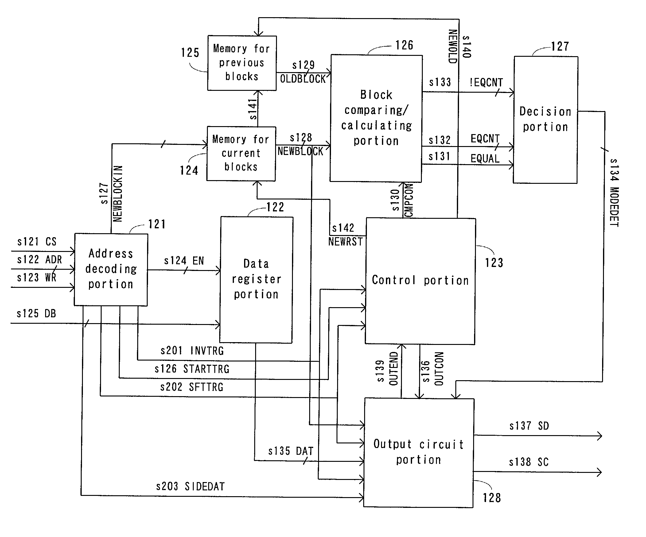
[0044][Constitution] Next, the second embodiment of this invention will be described with reference to the attached drawings. FIG. 13 is a block diagram of the data transmission controller of an image forming system based on thermal ink jet printing representing a second embodiment. The data transmission controller of the second embodiment shown in FIG. 13 is different from the corresponding controller of the first embodiment shown in FIG. 4 in that, in the former, an address decoding portion creates an invert trigger s201, shift trigger s202 and side data s203, and deliver them as output. Otherwise the former is the same with the latter. Hence, the elements of the second embodiment having functions similar to those of the first embodiment will be represented by the same symbols, and their detailed description will be omitted. The elements of the second embodiment similar to those of the first embodiment will be omitted from further description. The invert trigger s201 carries an in...


PUM


Abstract

A method and system for serial communication capable of increasing the speed of the transmission of serial data are provided. A block mode is employed if transmission of serial data having a specific length is required, and under which data to be transmitted are divided into plural blocks, and firstly transmitted is block information that notifies which blocks out of the entire blocks will be transmitted, and then transmitted are the data included in the blocks notified by the block information. The burst mode is a mode under which the block information which is currently transmitted is compared with the block information which was previously transmitted, and, if the two are the same, transmission of the data is introduced, while the block information being omitted. The system attached mode information notifying the mode through which data will be transmitted, to the data to be transmitted.

Description

TECHNICAL FIELD[0001]The present invention relates to a method for synchronous serial communication whereby it is possible to transmit serial data in synchrony with timing signals, and a system for synchronous serial communication based on the use of the method.BACKGROUND ART[0002]The method for serial communication has been known as one of the methods for transmitting data serially, and many variations of the method have been devised. Serial data communication is characterized by that it requires a comparatively few communication lines, and that it allows comparatively easy data control. Because of these features, the method for serial data communication has been widely adopted by the communication systems of various fields.[0003]However, serial data communication requires a comparatively long time if data to be transmitted are large in volume. Further, if a series of data have been dispatched, and a change must be added to the data later, usually all the data including the change ...

Claims


Application Information

Patent Timeline
Patent Type & Authority Patents(United States)
IPC IPC(8): H04L7/00G06F13/38G06F3/12H04L1/00
CPCH04L1/0084
Inventor FUKUDA, MICHITAKA
Owner COPYER
Why Eureka
Try Eureka