
Serial interface apparatus performing asynchronous serial data transfer using asynchronous serial communication method

a serial communication and serial data technology, applied in the field of serial interface apparatus, can solve the problems of increasing the chip area of the lsi, the drawback of reducing the number of components and the size, and the increase in hardware cost, so as to achieve the effect of reducing the hardware cost of each apparatus

Inactive Publication Date: 2008-07-03
PANASONIC CORP
View PDF20 Cites 12 Cited by
  • Summary
  • Abstract
  • Description
  • Claims
  • Application Information

AI Technical Summary

Benefits of technology

[0027]Therefore, according to a serial interface apparatus, a bidirectional serial interface system using the same serial interface apparatus, and a serial communication method for the serial interface apparatus according to the present invention, by providing the above-mentioned configuration, half-duplex or full-duplex, bidirectional, asynchronous serial data communication equivalent to the UART interface related to the prior art can be realized by using two signal terminals which are less in number than the prior art, and this leads to that cost of hardware of each apparatus can be largely reduced. Furthermore, providing the above-mentioned first and second level adjusting circuits allows the data communication by adjusting output voltage even when source voltage is different from that of other side apparatuses.

Problems solved by technology

However, in the data communication apparatuses with the bidirectional serial interface system related to the prior art, since a port for every four terminals has to be provided on the LSI side every time the function is added, and as a result, chip area of the LSI increases, resulting in cost-up of hardware and drawbacks in reducing the number of components and the size.

Method used


Image

  • Serial interface apparatus performing asynchronous serial data transfer using asynchronous serial communication method
  • Serial interface apparatus performing asynchronous serial data transfer using asynchronous serial communication method
  • Serial interface apparatus performing asynchronous serial data transfer using asynchronous serial communication method

Examples


first preferred embodiment

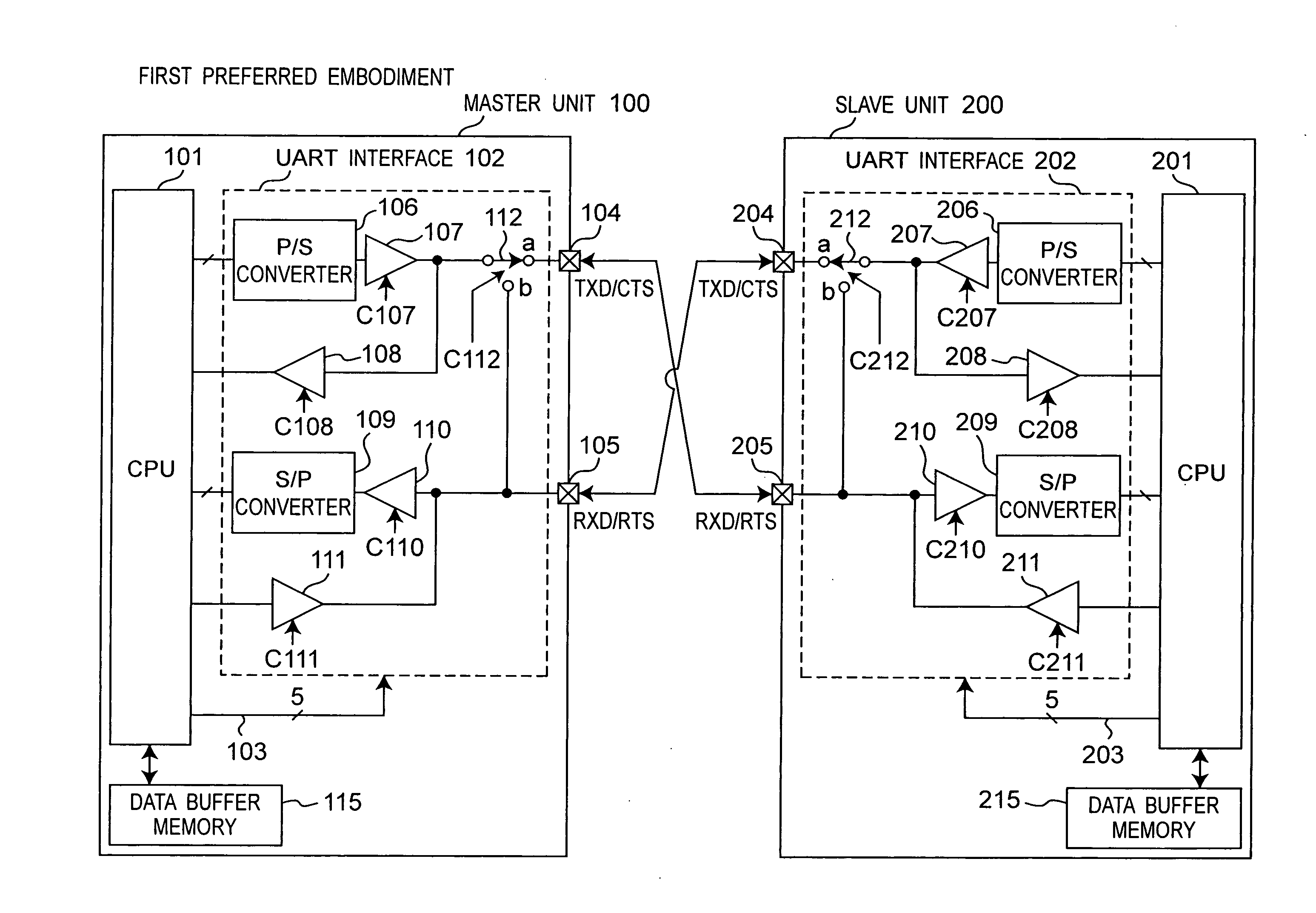
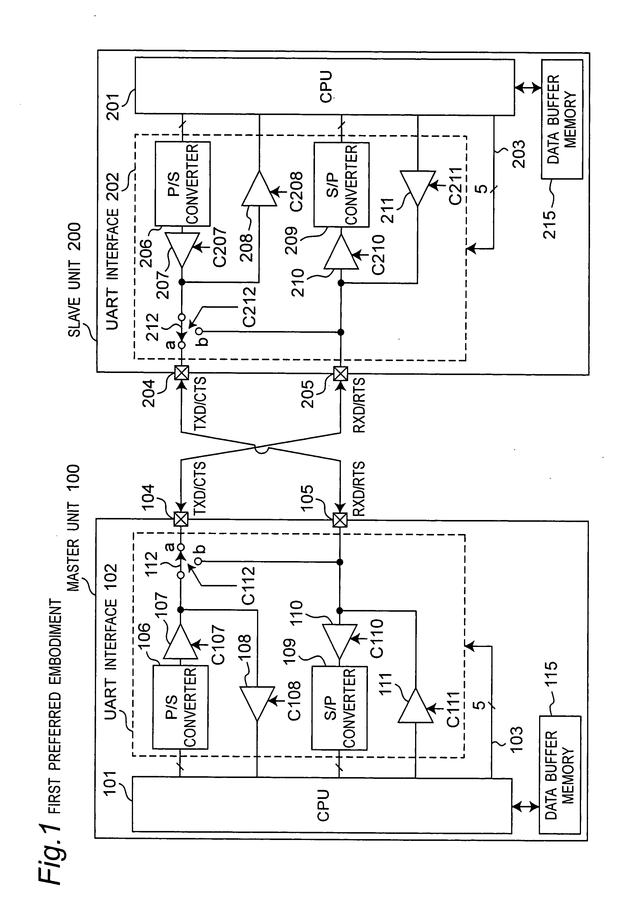
[0048]FIG. 1 is a block diagram showing a configuration of a bidirectional serial interface system composed of a master unit 100 and a slave unit 200 according to a first preferred embodiment of the present invention. As shown in FIG. 1, it is characterized in that the bidirectional serial interface system according to the first preferred embodiment is composed of the master unit 100 which is, for example, a portable information terminal apparatus or a personal computer or the line, and the slave unit 200 which is an external apparatus such as a PDA or a communication terminal apparatus. The master unit 100 has respectively shared two signal terminals 104 and 105. The slave unit 200 has respectively shared two signal terminals 204 and 205.

[0049]That is, the master unit 100 has following terminals:

[0050](a) a signal terminal (referred to as a TXD / CTS terminal hereinafter) 104 shared by a TXD signal terminal and a CTS signal terminal; and

[0051](b) a signal terminal (referred to as an ...

second preferred embodiment

[0078]FIG. 6 is a block diagram showing a configuration of a bidirectional serial interface system composed of a master unit 100A and a slave unit 200A according to a second preferred embodiment of the present invention. The bidirectional serial interface system according to the second preferred embodiment shown in FIG. 6 differs in the following points as compared with the bidirectional serial interface system according to the first preferred embodiment shown in FIG. 1:

[0079](a) The master unit 100A includes a CPU 101A in place of the CPU 101, and the slave unit 200A includes a CPU 201A in place of the CPU 201;

[0080](b) The master unit 100A includes a UART interface 102A in place of the UART interface 102, and the slave unit 200A includes a UART interface 202A in place of the UART interface 202;

[0081](b1) In order to make the UART interface 102A operate even when the master unit 100A and the slave unit 200A are different in source voltage, level adjusting circuits 130 and 140 for a...

third preferred embodiment

[0099]FIG. 10 is a block diagram showing a configuration of a bidirectional serial interface system composed of a master unit 100B and a slave unit 200B according to a third preferred embodiment of the present invention. The bidirectional serial interface system according to the third preferred embodiment shown in FIG. 10 differs in the following points as compared with the bidirectional serial interface system according to the second preferred embodiment shown in FIG. 6:

[0100](a) The master unit 100B includes the CPU 101B in place of the CPU 101A, and the slave unit 200B includes a CPU 201B in place of the CPU 201A;

[0101](b) The master unit 100B includes a UART interface 102B in place of the UART interface 102A, and the slave unit 200B includes a UART interface 202B in place of the UART interface 202A;

[0102](b1) In the UART interface 102A, a selector 151 and an S / P converter 152 are inserted between the CPU 101A and an output terminal of the buffer amplifier 108, and a selector 161...


PUM


Abstract

A serial interface apparatus includes a first signal terminal sharing a data transmitting terminal and a second control signal terminal, a second signal terminal sharing a data receiving terminal and a first control signal terminal, and first to fourth buffer amplifiers. Upon receiving two types of second control signals different from each other from the other side apparatuses after transmitting the first control signal to the other side apparatus, the controller executes half-duplex data communication using the two signal terminals by transmitting the serial data signal to the other side apparatus via the first signal terminal, transmitting to the first signal terminal a serial data signal indicating a notice of termination upon end of the serial data signal to be transmitted, and judging as a data communication termination upon reception of the second control signal from the other side apparatus in response to the transmission of the serial data signal.

Description

FIELD OF THE INVENTION[0001]The present invention relates to a serial interface apparatus that bidirectionally performs asynchronous serial data transfer using an asynchronous serial communication method such as Universal Asynchronous Receiver-Transmitter (referred to as UART hereinafter), a bidirectional serial interface system using the serial interface apparatus, and a serial communication method for use in the serial interface apparatus.DESCRIPTION OF THE RELATED ART[0002]In recent years, portable information apparatuses are required for user convenience by connecting to a plurality of external apparatuses in response to various application functions. Currently, serial data communication generally using UART has been widely used.[0003]First of all, a bidirectional serial interface system consisted of a master unit 300 and a slave unit 400 using a UART interface according to the prior art disclosed in Japanese Patent Laid-open Publication No. 2003-5874 and Japanese Patent Laid-op...

Claims


Application Information

Patent Timeline
IPC IPC(8): H04L5/22
CPCG06F13/4286H04L5/16H04L5/1415
Inventor FUNAGAI, KENICHI
Owner PANASONIC CORP
Learn More