Asynchronous serial communication method and asynchronous serial communication device

a serial communication and synchronous technology, applied in the direction of synchronisation signal speed/phase control, duplex signal operation, instruments, etc., can solve the problems of high-frequency clocking heat concentration and clock skew problems, reduce the overhead time, reduce the size of the circuit, and reduce the number of signal lines.

Inactive Publication Date: 2008-05-08
SEIKO EPSON CORP
View PDF6 Cites 10 Cited by
  • Summary
  • Abstract
  • Description
  • Claims
  • Application Information

AI Technical Summary

Benefits of technology

[0011]An advantage of the present invention is to provide an asynchronous serial communication method with which the number of signal lines can be reduced while obtaining a high-speed communication to a certain extent and the size of the circuit can be reduced. Another advantage of the invention is to provide an asynchronous serial communication device thereof.
[0012]An asynchronous serial communication method according to a first aspect of the invention includes a sender transmitting a one bit of serial data by firstly making a signal transition on the data line, secondly putting the one bit of serial data on the data line after a predetermined time T1 yet before another predetermined time T1+T2, and a receiver receiving the one bit of serial data by firstly detecting the signal transition on the data line and secondly capturing the one bit of serial data after a predetermined tune T3 (where T3>T1+T2).
[0013]According to the first aspect, when a sender transmitting a one bit of serial data makes a signal transition on the data line, the receiver detects the signal transition on the data line and captures a one-bit data sent by the sender after a predetermined time. Even though each data bit is accompanied with a preceding signal transition, the overhead time can be so small that an impact on the bandwidth is negligible. Therefore, it is possible to perform an asynchronous serial communication at a high speed to a certain extent with two communication wires: a data wire and a acknowledge wire, without a control wire. According to this asynchronous serial communication method, no complicated signal processing is required so that it is possible to reduce the size of a circuit.
[0014]An asynchronous serial communication method according to a second aspect of the invention includes a sender transmitting a one bit of serial data by firstly changing a signal level of the data line from a default level to the opposite level and then putting the one bit of serial data on the data line after a predetermined time T1 yet before another predetermined time T1+T2, and a receiver receiving the one bit of serial data by firstly detecting the signal transition on the data line and secondly capturing the one bit of serial data after a predetermined time T3 (where T3>T1+T2).
[0015]In this way, it is possible to perform an asynchronous serial communication at a high-speed to a certain extent with two communication wires: a data wire and a acknowledge wire, without a control wire. According to this asynchronous serial communication method, the size of a circuit can be reduced.
[0016]An asynchronous serial communication device according to a third aspect of the invention includes a sender communication port transmitting a one bit of serial data by firstly making a signal transition on the data line, secondly putting the one bit of serial data on the data line after a predetermined time T1 yet before another predetermined time T1+T2, and a receiver communication port receiving the one bit of serial data by firstly detecting the signal transition on the data line and secondly capturing the one bit of serial data after a predetermined time T3 (where T3>T1+T2), wherein the sender communication port and the receiver communication port are coupled each other through a single data line.

Problems solved by technology

Recently as the chip size increases as well as the number of transistors integrated in a chip, the heat concentration and clock skew problems caused by high-frequency clocking have become serious matters.
The limitations of synchronous circuit design techniques have been realized especially with the deep-submicron technologies.
The penalty for reducing the power consumption is circuit cost at the receiver.
The sampling clock ironically can increase the power consumption at the receiver, again.
However, since any conventional asynchronous communication method between asynchronous devices has pros and cons, no asynchronous communication method has established its position yet.
Disadvantages of the former are that three signal lines (two data lines and one control line) are required for 1-bit data communication, which means that an extra signal line is needed and that the circuit structure is complicated compared with synchronous communication methods.
Disadvantages of the latter are that three signal lines (one data line and two control lines) are required for 1-bit that a communication and that the communication speed is deteriorated by a delay element.

Method used


Image

  • Asynchronous serial communication method and asynchronous serial communication device
  • Asynchronous serial communication method and asynchronous serial communication device
  • Asynchronous serial communication method and asynchronous serial communication device

Examples


first embodiment

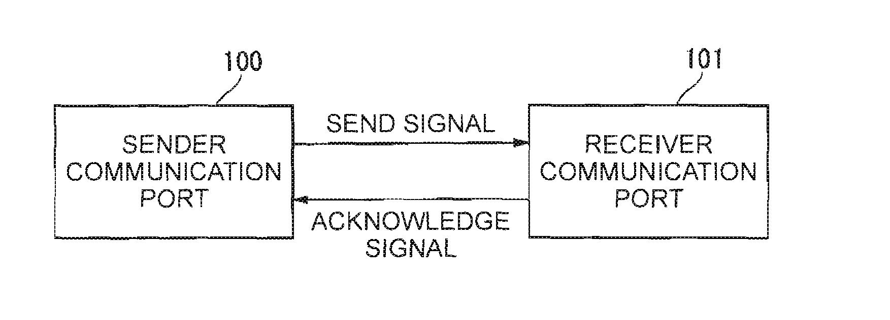
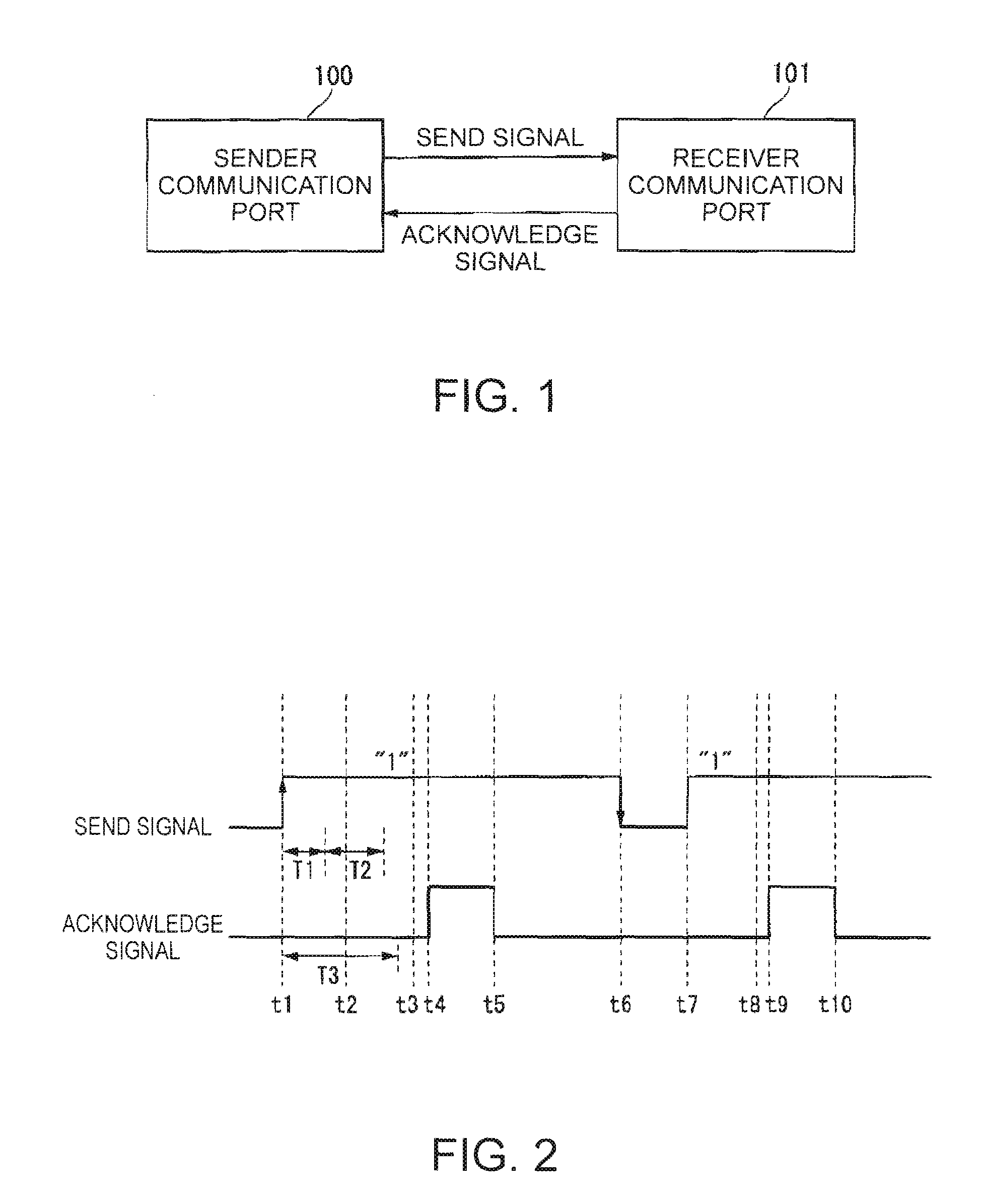
[0065]FIG. 1 is a block diagram of an asynchronous serial communication device which performs communication in accordance with an asynchronous serial communication method according to a first embodiment of the invention.

[0066]Referring to FIG. 1, the reference number 100 denotes a sender communication port and the reference number 101 denotes a receiver communication port. The sender communication port 100 and the receiver communication port 101 are coupled each other through a data wire (a communication wire) that transmits a send signal and through an acknowledge wire that transmits an acknowledge signal. The asynchronous serial communication device is formed in this way.

[0067]In the asynchronous serial communication device, the sender communication port 100 sends a send signal to the receiver communication port 101. The receiver communication port 101 receives the send signal and sends an acknowledge signal to the sender communication port 100. The asynchronous serial communicati...

second embodiment

[0136]A second embodiment of the invention is now described with reference to FIG. 17.

[0137]FIG. 17 is a wave form diagram of the send signal and the acknowledge signal which are sent in accordance with an asynchronous serial communication method according to the second embodiment of the invention. FIG. 17 shows a send signal sent by the sender communication port 100 and a acknowledge signal sent by the receiver communication port 101.

[0138]The sender communication port 100 firstly shifts the signal level of the send signal from “0” to “1” (a predetermined level) (at time ti). At this point, the receiver communication port 101 detects the signal level shift of the send signal.

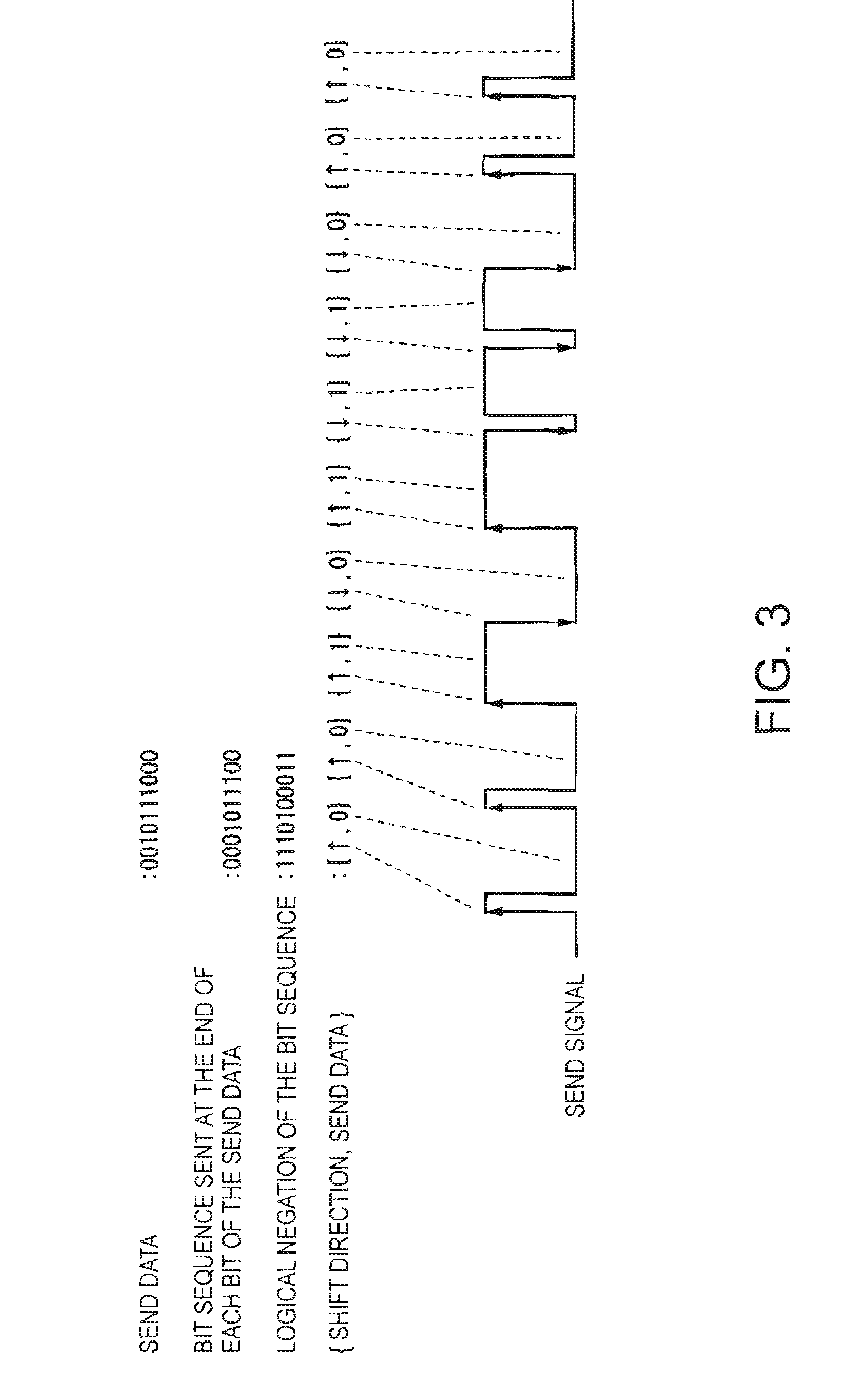
[0139]The sender communication port 100 retains the signal level “1” of the send signal for a predetermined time period (the first time period T1) or a longer time period, and it then transmits a 1-bit send data within a predetermined time period (the second time period T2). In the example shown in FIG. 17, the...


PUM


Abstract

An asynchronous serial communication method and the apparatus including a sender transmitting a one bit of serial data by firstly making a signal transition on the data line, secondly putting the one bit of serial data on the data line after a predetermined time T1 yet before another predetermined time T1+T2, and a receiver receiving the one bit of serial data by firstly detecting the signal transition on the data line and secondly capturing the one bit of serial data after a predetermined time T3 (where T3>T1+T2).

Description

[0001]The entire disclosure of Japanese Patent Application No. 2006-298806, filed Nov. 2, 2006 is expressly incorporated by reference herein.BACKGROUND OF THE INVENTION[0002]1. Technical Field[0003]Several aspects of the present invention relate to an asynchronous serial communication method and an asynchronous serial communication device.[0004]2. Related Art[0005]An asynchronous circuit has been known for about 50 years. An asynchronous state machine, a calculating machine and the like using delay elements have been developed. However, after the synchronous design method which uses the global clock signal to drive a circuit was introduced in the 1970s so many kinds of small-scale integrated (SSI) circuit and medium-scale integrated (MSI) circuit driven by the global clock signal were developed that the synchronous circuit design techniques became dominant, while the asynchronous circuit design techniques have disappeared in the industry.[0006]Recently as the chip size increases as ...

Claims


Application Information

Patent Timeline
Patent Type & Authority Applications(United States)
IPC IPC(8): H04B1/38H04L5/16H04L7/04
CPCH04L25/4906H04L12/28H04L65/00
Inventor KARAKI, NOBUO
Owner SEIKO EPSON CORP
Why Eureka
Try Eureka