
High-precision phase and frequence measuring system

A frequency measurement, high-precision technology, applied in frequency measurement devices, measurement devices, measurement of electrical variables, etc., can solve the problems of measurement accuracy depending on the frequency of the reference clock and low measurement accuracy

Active Publication Date: 2013-04-24
BEIJING RES INST OF TELEMETRY +1
View PDF5 Cites 11 Cited by
  • Summary
  • Abstract
  • Description
  • Claims
  • Application Information

AI Technical Summary

Problems solved by technology

[0014] The technical problem of the present invention is to overcome the problem that the measurement accuracy of the traditional conventional rough counting method is too low, and the measurement accuracy depends on the frequency of the reference clock, and provide a high-precision phase and frequency measurement system

Method used


Image

  • High-precision phase and frequence measuring system
  • High-precision phase and frequence measuring system
  • High-precision phase and frequence measuring system

Examples


Embodiment Construction

[0064] Below in conjunction with accompanying drawing and example the present invention is described in detail, specifically as follows:

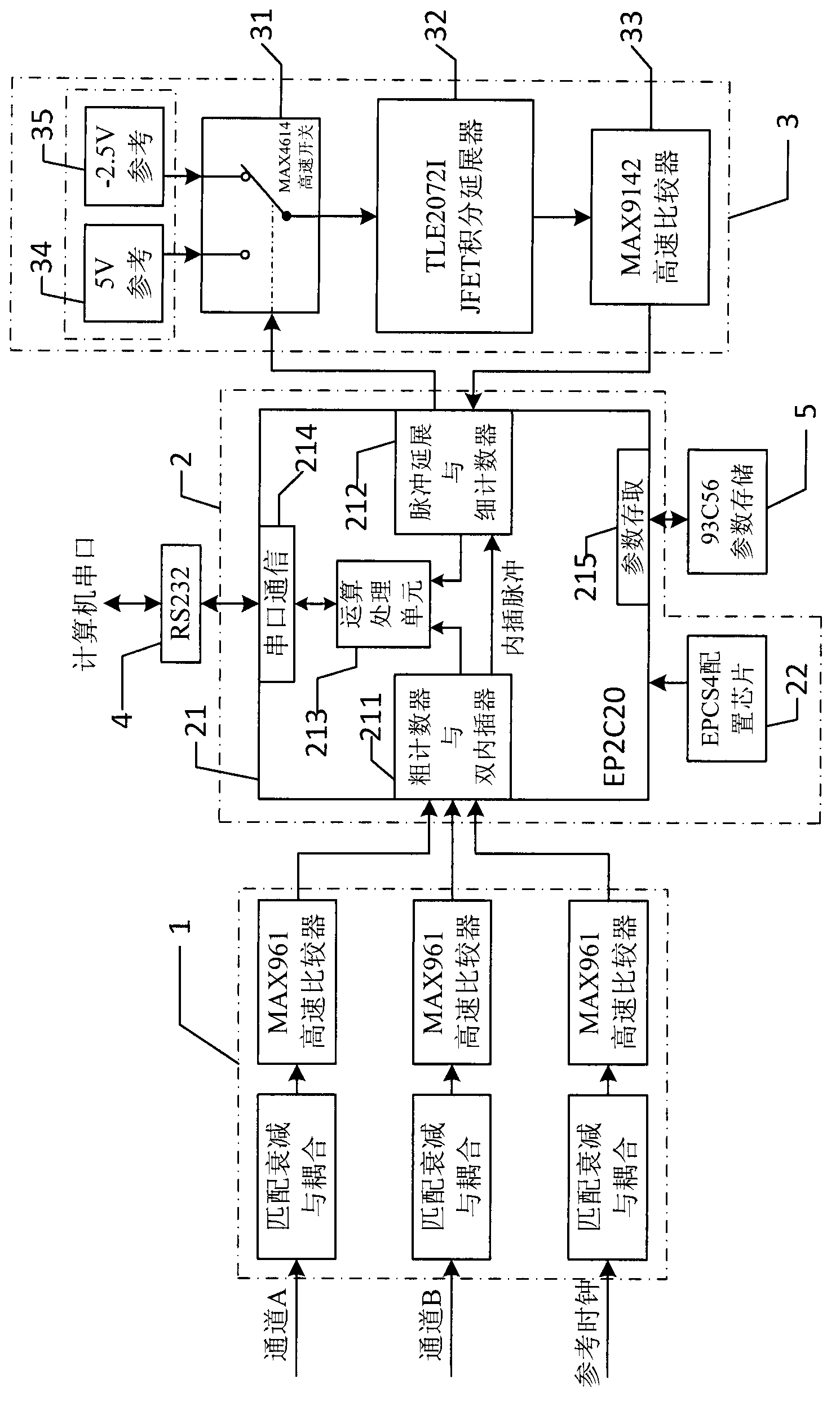
[0065] Such as figure 1 As shown, the hardware circuit of the present invention is mainly composed of an input signal conditioning circuit 1 , an FPGA circuit 2 , an integral analog extension circuit 3 , a serial port communication circuit 4 and a parameter storage circuit 5 .

[0066] 1. Input signal conditioning circuit 1

[0067] The input signal conditioning circuit 1 is connected to the external input channel A signal, channel B signal and reference clock signal, and converts the three input signals into CMOS standard level pulse signals respectively, and sends them to the FPGA circuit 2 . Each channel specifically includes a resistance matching / attenuation circuit, an AC / DC coupling circuit and a high-speed comparator circuit. The impedance matching and attenuation of the input signal use a Π-type resistor network. The coupling of...


PUM


Abstract

Provided is a high-precision phase and frequence measuring system. An input signal conditioning circuit in the system respectively converts a channel A signal, a channel B signal and a reference clock signal from external input into pulse signals and sends the pulse signals to a field programmable gata array (FPGA) circuit. The FPGA circuit makes a rough count measurement on the time interval between the treated channel A signal and the channel B signal and generates two interpolating pulses at the beginning and the end of the time interval and respectively outputs two interpolating pulses into an integral analog extension circuit. Two integral pulses sent back from the integral artificial extension circuit are received, a count measurement on the pulses which are sent back are respectively made, combining the count measurement and delay correction parameters to obtain phases and frequencies of the A signal and the B signal through calculations, and the phases and frequencies are sent to a host computer through an asynchronous serial communication circuit. The integral extension circuit forms an integral voltage according to the interpolating pulses, compares, reforms and sends the integral voltage to the FPGA circuit. The asynchronous serial communication circuit is used for communicating with host computer serial ports and a parameter storing circuit is used for storing delay correction parameters.

Description

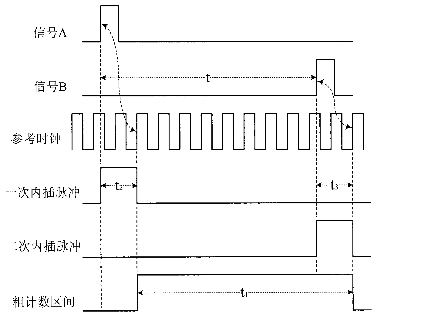
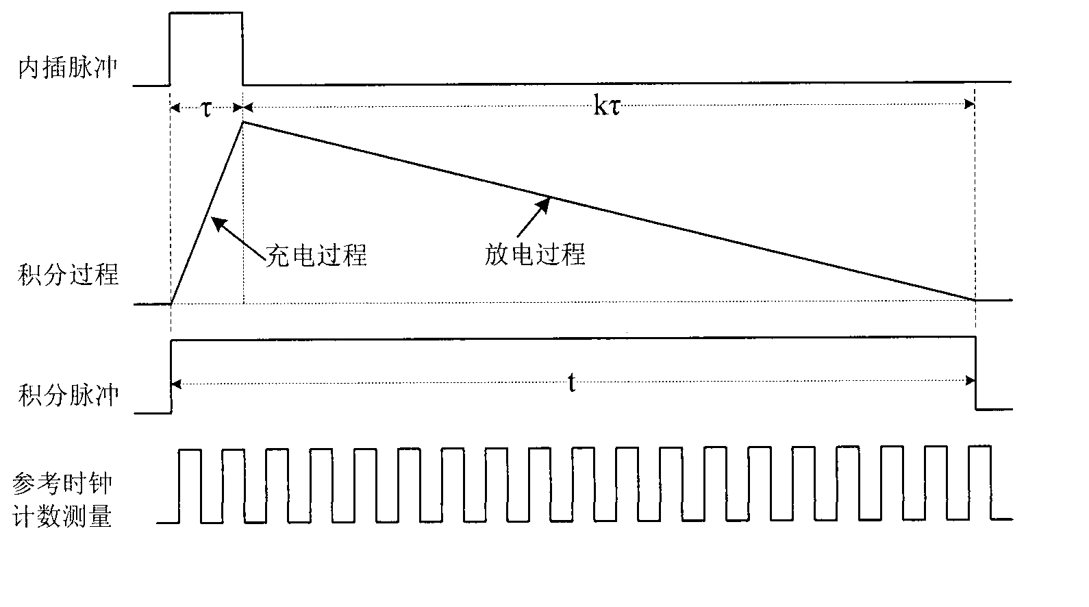
technical field [0001] The present invention relates to a high-precision phase and frequency measurement technology. Based on the traditional rough counting measurement method, the double interpolation method and the integral analog extension method are used comprehensively to divide the time interval to be measured into three parts for precise measurement, so that The measurement resolution of the time interval reaches 50ps, and the measurement range can cover 50ps to any long time interval. This technology has very extensive and key applications in the field of traditional telecommunication engineering practice and nuclear physics theory research, especially in the field of aerospace military technology such as modern laser ranging system and satellite positioning and navigation system. Background technique [0002] Phase and frequency are two important physical parameters of signals, and they are required to be precisely measured in many modern engineering practice and th...

Claims


Application Information

Patent Timeline
IPC IPC(8): G01R25/00G01R23/02
Inventor 孙高建龚立东顾兴旺杜亚珍王佳佳孙甲琦李树忠
Owner BEIJING RES INST OF TELEMETRY
Learn More