A double row time grating linear displacement sensor

A linear displacement and sensor technology, applied in instruments, measuring devices, electrical devices, etc., can solve the problems of reducing the measurement accuracy of the linear displacement sensor, complex sensor system structure, affecting the quality of the induction signal, etc., achieving simple structure and measurement resolution. High force and the effect of eliminating the influence of high-order harmonics

Active Publication Date: 2018-11-13
CHONGQING UNIV OF TECH
View PDF5 Cites 0 Cited by
  • Summary
  • Abstract
  • Description
  • Claims
  • Application Information

AI Technical Summary

Problems solved by technology

When the space equivalent of the interpolation clock pulse reaches a certain limit, in order to further improve the resolution, the only way to further increase the number of pole pairs of the sensor is, as a result, the structure of the sensor system is complicated and the manufacturing cost is high.
[0004] At present, the time grating linear displacement sensor that has been developed adopts the form of machined wire groove and winding, which is difficult and costly to increase the number of poles, and the harmonic analysis method is used for the electromagnetic rectangular wave signal, mainly considering the The role of the fundamental wave signal, the high-order harmonics in the electromagnetic rectangular wave signal will affect the quality of the induction signal and reduce the measurement accuracy of the linear displacement sensor

Method used


Image

  • A double row time grating linear displacement sensor
  • A double row time grating linear displacement sensor
  • A double row time grating linear displacement sensor

Examples


Embodiment Construction

[0018] The present invention will be described in detail below in conjunction with the accompanying drawings.

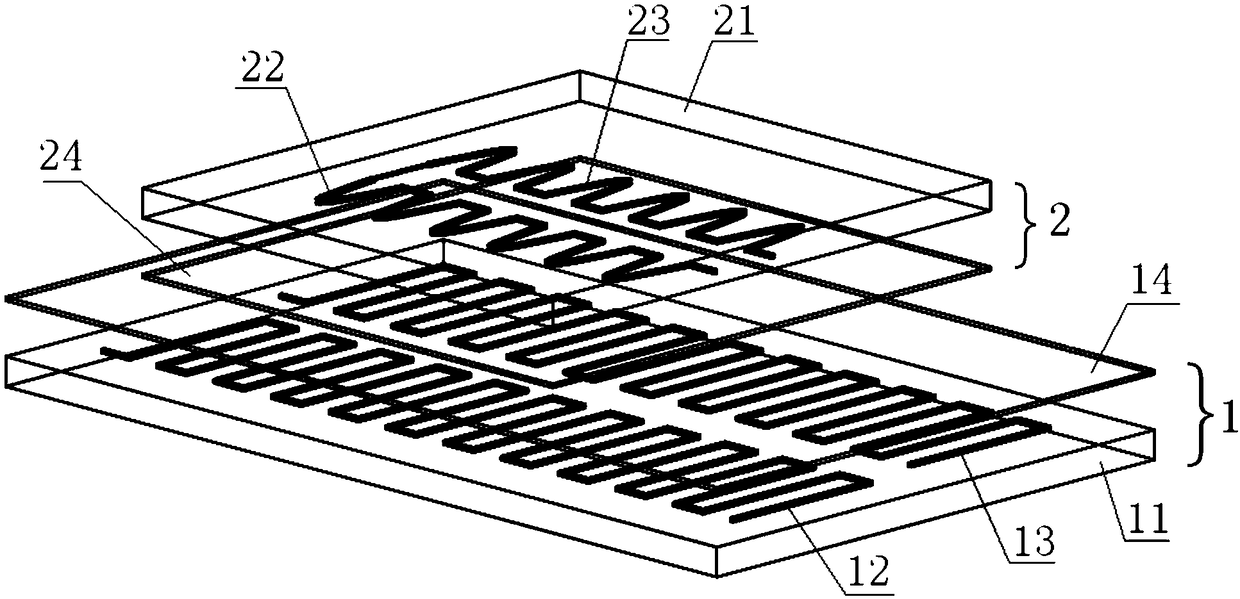
[0019] Such as Figure 1 to Figure 5 The shown dual-row time grating linear displacement sensor includes a fixed scale 1 and a moving scale 2 parallel to the fixed scale 1 with a gap of 0.2 mm.

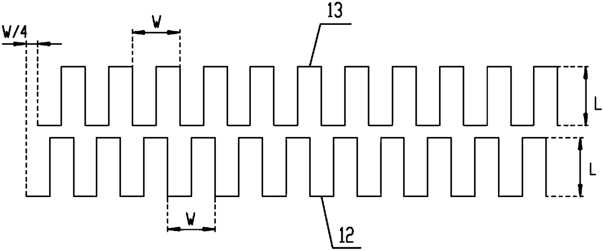
[0020] The scale 1 includes a scale base 11, a first excitation coil 12 arranged in the wiring layer on the side of the scale base 11 opposite to the moving scale, a second excitation coil 13 and a scale insulation layer 14 arranged on the wiring layer , the first excitation coil 12 and the second excitation coil 13 are parallel to each other along the measurement direction, the projection of the fixed-length substrate 11 can completely cover the first excitation coil 12 and the second excitation coil 13, and the thickness of the fixed-length substrate 11 is equal to (or It is a non-magnetic substrate larger than 2 mm, made of ceramic materials; the first excitation coil 12...


PUM


Abstract

The invention discloses a double-column-type time-grating linear displacement sensor. The sensor comprises a fixed ruler and a moving ruler. The fixed ruler comprises a fixed ruler matrix and first and second exciting coils. The first and second exciting coils are winded as a rectangular wave along a measurement direction. The moving ruler comprises a moving ruler matrix and first and second induction coils. The first and second induction coils are winded as a half-sine winding mode. The first and second induction coils directly face and are parallel to the first and second exciting coils. Two phase symmetry excitation currents flow into the first and second exciting coils. When the moving ruler moves relative to the fixed ruler, the first and second induction coils output two paths of induction signals. Through series connection and superposition, a travelling wave signal is formed. And then the travelling wave signal carries out phase comparison with a same frequency reference signal, a phase difference is expressed by an interpolated high frequency clock pulse number, and after conversion, a linear displacement is acquired. The structure of the sensor is simple, measurement resolution is high, batch manufacturing is easy to achieve and cost is low.

Description

technical field [0001] The invention belongs to the technical field of precision measurement sensors, and in particular relates to a double row time grating linear displacement sensor. Background technique [0002] Linear displacement measurement is the most basic geometric quantity measurement, and it exists in a large number in industrial and scientific practices represented by manufacturing. Precision linear displacement measurement mainly uses linear displacement sensors, such as gratings, magnetic gratings, capacitive gratings, etc. These sensors obtain the displacement by counting the grid lines that are evenly divided in space, and their common feature is the use of high-density, ultra-precision space The grid lines are used to meet the resolution requirements of small displacements. In order to further improve the measurement resolution and measurement accuracy of the sensor, in addition to relying on advanced scribing technology to increase the scribing density, it...

Claims


Application Information

Patent Timeline
Patent Type & Authority Patents(China)
IPC IPC(8): G01B7/02
CPCG01B7/02
Inventor 杨继森刘小康高义张静李明李路健
Owner CHONGQING UNIV OF TECH
Why Eureka
Try Eureka