
Image-rejection I/Q demodulators

a demodulator and image technology, applied in the field of digital communication systems, can solve the problems of increasing the degree of mismatch between the i and q channels, affecting and affecting the degree of mismatch between the devices on the semiconductor wafer, so as to reduce the image response of the receiver

Inactive Publication Date: 2007-02-27
AVAGO TECH INT SALES PTE LTD
View PDF14 Cites 14 Cited by
  • Summary
  • Abstract
  • Description
  • Claims
  • Application Information

AI Technical Summary

Benefits of technology

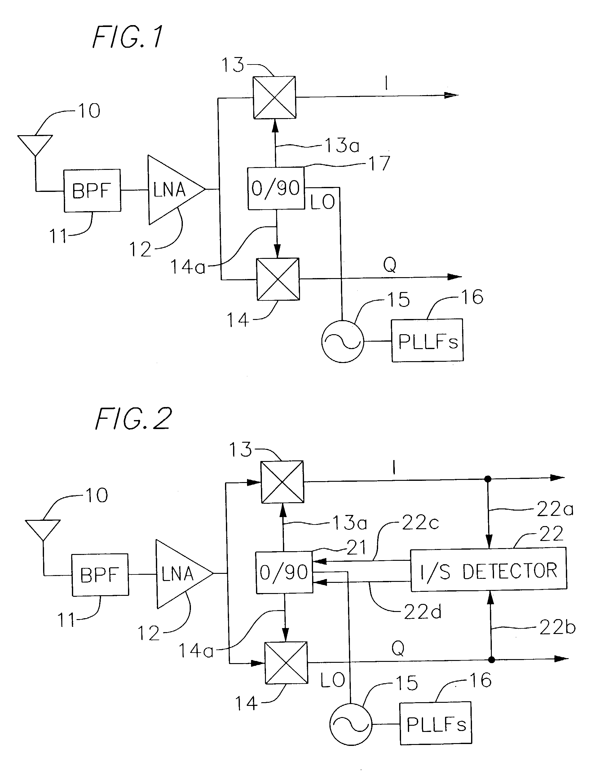
[0021]The invention may also be practiced as a method for adjusting the image response of a communications receiver that includes in-phase (I) and quadrature (Q) demodulators. The method comprises the acts: synthesizing an LO signal; deriving an LO_I signal from the LO signal; deriving an LO_Q signal from the LO signal; detecting an amplitude control signal that results from an amplitude mismatch between an I channel and a Q channel of the communications receiver; detecting a phase control signal that results from a phase mismatch between the I channel and the Q channel; adjusting the relative amplitudes of the LO_I and the LO_Q signals in response to the amplitude control signal; and adjusting the relative phases of the LO_I and the LO_Q signals in response to the phase control signal, wherein the adjustments to the relative respective amplitudes and the relative respective phases of the LO_I and LO_Q signals operate to compensate for mismatch between the I channel and the Q channel in a manner that reduces the image response of the receiver.

Problems solved by technology

Because state-of-the art semiconductor device design and fabrication does not admit of perfect matching between devices, even devices on the same die, some degree of mismatch between the I and Q channels is inevitable.
In fact, the mismatch between devices on a semiconductor wafer is known to be dependent on the physical size of the devices.
Because lower frequencies of operation permit larger device geometries, mismatch in a receiver IF section tends to be ameliorated as the IF is reduced.
In systems implemented with CMOS technology, virtually mandatory when power consumption is a paramount design consideration, not even this level of performance is realizable.
This detriment derives from the fact that CMOS devices tend to demonstrate less favorable matching characteristics.
Given that a 35 db image rejection specification is considered marginal for most digital communication receiver applications, the problems confronted in a CMOS-based design are glaringly apparent.

Method used


Image

  • Image-rejection I/Q demodulators
  • Image-rejection I/Q demodulators
  • Image-rejection I/Q demodulators

Examples


Embodiment Construction

[0032]For a thorough understanding of the subject invention, reference is made to the following Description, including the appended Claims, in conjunction with the above described Drawings.

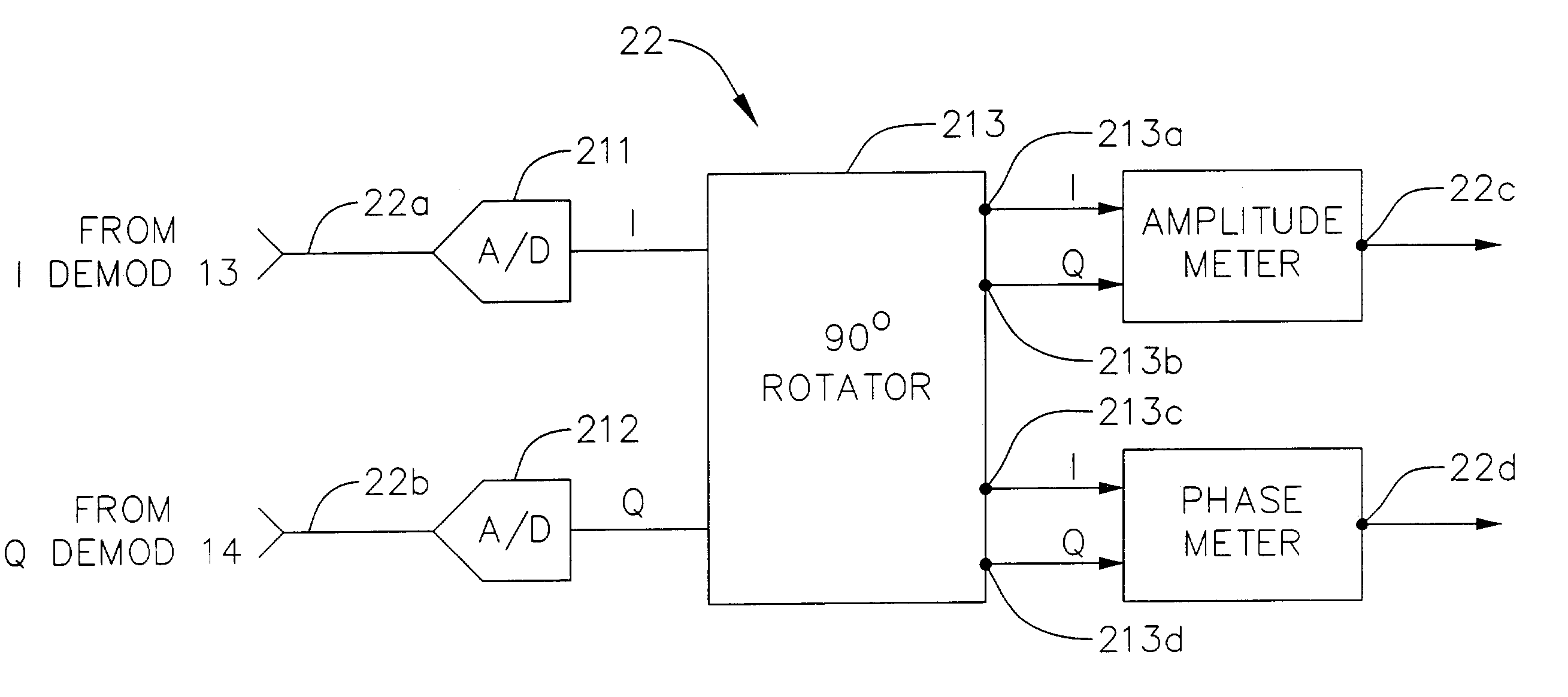
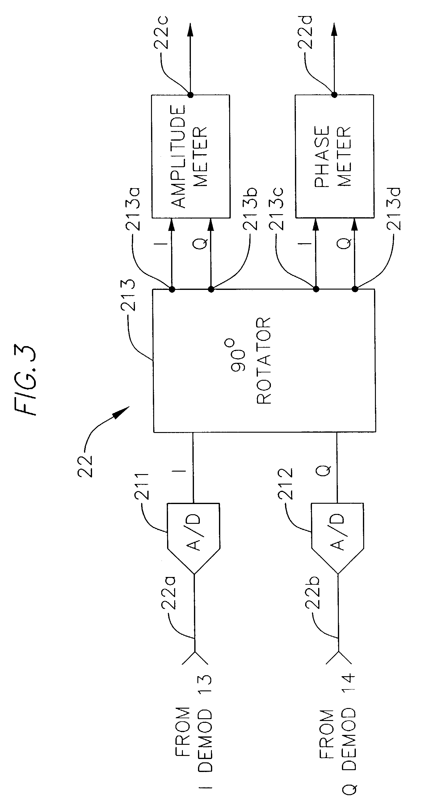
[0033]Referring now to FIG. 2, the subject receiver with image-rejection digital I / Q demodulator is seen to be in many respects similar to the digital I / Q demodulation receiver depicted in FIG. 1. A salient departure is the substitution of the phase shifter 17 in FIG. 1 with the quadrature LO generator 21 in the receiver of FIG. 2. In addition, and in a manner to be more completely described below, the operation of quadrature LO generator 21 is controlled by an image / signal ratio (I / S) detector 22 that applies amplitude control and phase control signals to quadrature LO generator 21 in a manner that adjusts the LO_I and LO_Q signals to the I demodulator 13 and to the Q demodulator 14 respectively, so as to reduce the image response of the receiver.

[0034]With continued reference to FIG. 2, operatio...


PUM


Abstract

In a communications receiver for quadrature demodulation, a feedback technique for reducing the image response of the receiver. The communications receiver includes an I demodulator and a Q demodulator. A local oscillator (LO) signal is provided by a PLL to a quadrature LO generator that provides an LO_I signal to an I demodulator and an LO_Q signal to a Q demodulator. The LO_I and LO_Q signals are amplitude and phase-controlled versions of the LO signal. An image / signal ratio (I / S) detector detects the relative phase difference and the relative amplitude difference between the respective output terminals of the I demodulator and the Q demodulator and applies an amplitude control signal and a phase control signal to corresponding amplitude control and phase control inputs of the quadrature LO generator. The I / S detector calibrates the quadrature LO generator during the interstitial interval between the reception of data packets. The control signals from the I / S detector adjust the relative amplitude and phase of the LO_I and LO_Q signals in a manner that reduces the image response of the communications receiver.

Description

CROSS-REFERENCE TO RELATED APPLICATION[0001]The present application is a continuation of patent application Ser. No. 09 / 591,925, filed Jun. 12, 2000 now U.S. Pat. No. 6,560,449, priority which is hereby incorporated by reference in its entirety.INCORPORATION BY REFERENCE[0002]This application, by this reference, hereby incorporates the following U.S. Patent Applications, in their entirety: U.S. patent application Ser. No. 09 / 592,016, filed Jun. 12, 2000; U.S. patent application Ser. No. 09 / 593,583, filed Jun. 12, 2000 and U.S. patent application Ser. No. 09 / 592,009, filed Jun. 12, 2000.FIELD OF THE INVENTION[0003]The invention relates to digital communications systems and, more particularly, to a technique for the reduction in the image response characteristics of an integrated circuit receiver that incorporates I / Q demodulation.BACKGROUND OF THE INVENTION[0004]I / Q (In-phase / Quadrature) modulators and demodulators are widely used in digital communications systems. I / Q demodulators a...

Claims


Application Information

Patent Timeline
IPC IPC(8): H04B1/10H04B17/00H04L27/00
CPCH04L27/0014H04L2027/0024H04L2027/0016
Inventor LIU, BIN
Owner AVAGO TECH INT SALES PTE LTD
Learn More