Apparatus for forming wave windings for rotor and stator lamination packets of electrical machines

a technology of electrical machines and forming tools, which is applied in the direction of electrical apparatus, dynamo-electric machines, electromagnets, etc., can solve the problems of excessive radial width and the inability to reduce using conventional winding head forming tools

Inactive Publication Date: 2007-03-06
ELMOTEC STATOMAT VERTRIEBS
View PDF18 Cites 18 Cited by
  • Summary
  • Abstract
  • Description
  • Claims
  • Application Information

AI Technical Summary

Benefits of technology

[0007]It is therefore the object of the invention to make a method and an apparatus available with the aid of which wave windings even made of comparatively thick winding wire can be produced and introduced into rotor or stator lamination packets in a simpler way.

Problems solved by technology

The difficulty in producing a stator of this kind is that the thick rectangular wire, whose width is equivalent to the slot width, can be deformed only with difficulty in a conventional winding and pulling-in process, and normally the winding heads that protrude from the face end beyond the stator lamination packet, because there are so many coil windings that overlap on the circumference and because of the poor deformability of the coil wire, add up to an excessively large radial width, which is practically impossible to reduce using conventional winding head forming tools.

Method used


Image

  • Apparatus for forming wave windings for rotor and stator lamination packets of electrical machines
  • Apparatus for forming wave windings for rotor and stator lamination packets of electrical machines
  • Apparatus for forming wave windings for rotor and stator lamination packets of electrical machines

Examples


Embodiment Construction

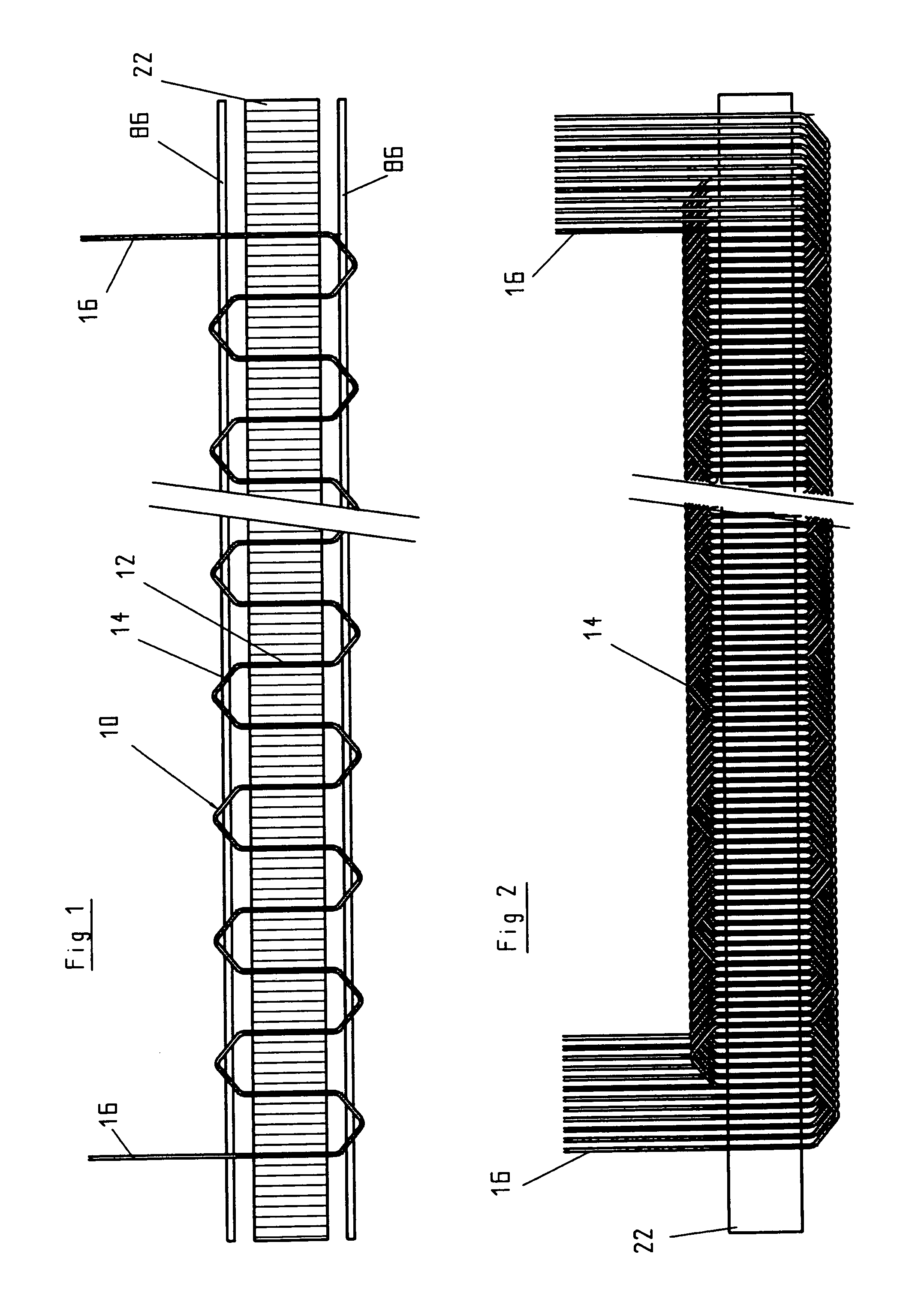
[0025]The wave winding 10 shown in FIG. 1 has a certain number of waves, formed by parallel straight portions 12 and gable-shaped winding heads 14, the number corresponding to the number and occupation of the slots in the rotor or stator lamination packet to be equipped with these windings. The connection ends of the wave winding are marked 16. In this example, with the wave winding 10 shown, every sixth slot of a stator lamination packet is occupied, and the straight portions 12 extend through the stator slots, while the gable- shaped winding heads 14 protrude from the stator lamination packet at the face end. Between two stator slots occupied by the wave winding 10, five stator slots remain free in this exemplary embodiment, and further such wave windings 10 are introduced into those slots. In all, it is for instance possible for there to be eight layers—this term being understood here to mean one wire layer in one slot 18—to be present in each of the radially inwardly open slots ...


PUM

PropertyMeasurementUnit
circumferenceaaaaaaaaaa
thicknessaaaaaaaaaa
shapeaaaaaaaaaa

Abstract

An apparatus in which wave windings with a defined number of waves are cut from a continuously formed wave winding band. In forming with a wire guide, the wave winding band is laid in alternation around the outer side faces of forming protrusions, offset from one another on the circumference of two disks. The two disks can be driven to rotate. In the angular range in which the wave winding band is driven on the circumference of the disks or roller, the spacing between one forming protrusion of one row and the next forming protrusion in the other row is increased by such an amount that the outer side faces of the forming protrusions form the winding heads of the wave windings. The wave windings cut from the wave winding band are introduced into radially outwardly open slots of a lamination packet or a rotorlike transfer tool.

Description

CROSS REFERENCE TO RELATED DOCUMENT[0001]The present application claims priority to Germany Application No. 103 28 955.0, filed on Jun. 27, 2003.BACKGROUND OF THE INVENTION[0002]1. Technical Fields[0003]The invention relates to a method and an apparatus for forming and introducing wave windings, with straight portions joined by winding heads, into rotor or stator lamination packets of electrical machines.[0004]2. The Related Art[0005]For a fairly long time, for instance from European Patent Disclosures EP 1 012 951 D1 and EP 0 604 792 A2 as well as U.S. Pat. No. 5,881,778, it has been known to create wave windings, in particular distributed wave windings for producing motor vehicle generators, using a winding nozzle revolving around a template or a template revolving in front of a fixed winding nozzle, and to draw the thus-formed annular wave windings axially into a stator.[0006]In the attempt to attain an optimal filling factor of the stator slots with as little copper as possible ...

Claims


Application Information

Patent Timeline
Patent Type & Authority Patents(United States)
IPC IPC(8): H02K15/02H02K15/10H02K15/04H02K15/06
CPCH02K15/0478H02K15/06Y10T29/49009Y10T29/49071Y10T29/49012Y10T29/49073H02K15/04
Inventor SADIKU, SADIK
Owner ELMOTEC STATOMAT VERTRIEBS
Why Eureka
Try Eureka