Solar energy power plant and method of producing electricity

a solar energy and power plant technology, applied in the field methods of producing electricity, can solve the problems of low efficiency of solar energy power plants, serious environmental problems, and few people being able to efficiently harness solar energy sources, and achieve the effects of improving efficiency, reducing heat loss, and improving efficiency

Inactive Publication Date: 2007-03-06
CONNELLY BRUCE
View PDF6 Cites 22 Cited by
  • Summary
  • Abstract
  • Description
  • Claims
  • Application Information

AI Technical Summary

Benefits of technology

[0031]An additional primary object of the present invention is to provide a power source that is safer than other power plants currently being used, by disclosing an invention that operates using water, an environmentally safe substance, water vapor and a steam turbine, all of which when combined as disclosed produce electricity and no environmental side affects.
[0032]Yet an additional primary object of the present invention is to improve on the short-comings of the earlier art and to advance the art by: disclosing a closed loop system that minimizes heat loss, and utilizes lost heat to produce electricity, making the invention more efficient; disclosing an invention that combines various environmentally safe energy producing structures, making the invention better for the environment; disclosing an invention that uses a heat exchange system, allowing the invention to continually produce power.

Problems solved by technology

Additionally, fossil fuels exist in a limited amount and are thought to create serious environmental problems.
However, very few people have been able to efficiently harness this energy source.
More specifically, none of these references disclose a rounded state change chamber, capillary tube and heat exchange system.
While, all of these references disclose devices that advance the science of solar energy, none of the devices has efficiently been able to provide inexpensive, consistent, and cost effective electrical energy from solar energy.

Method used


Image

  • Solar energy power plant and method of producing electricity
  • Solar energy power plant and method of producing electricity

Examples


Embodiment Construction

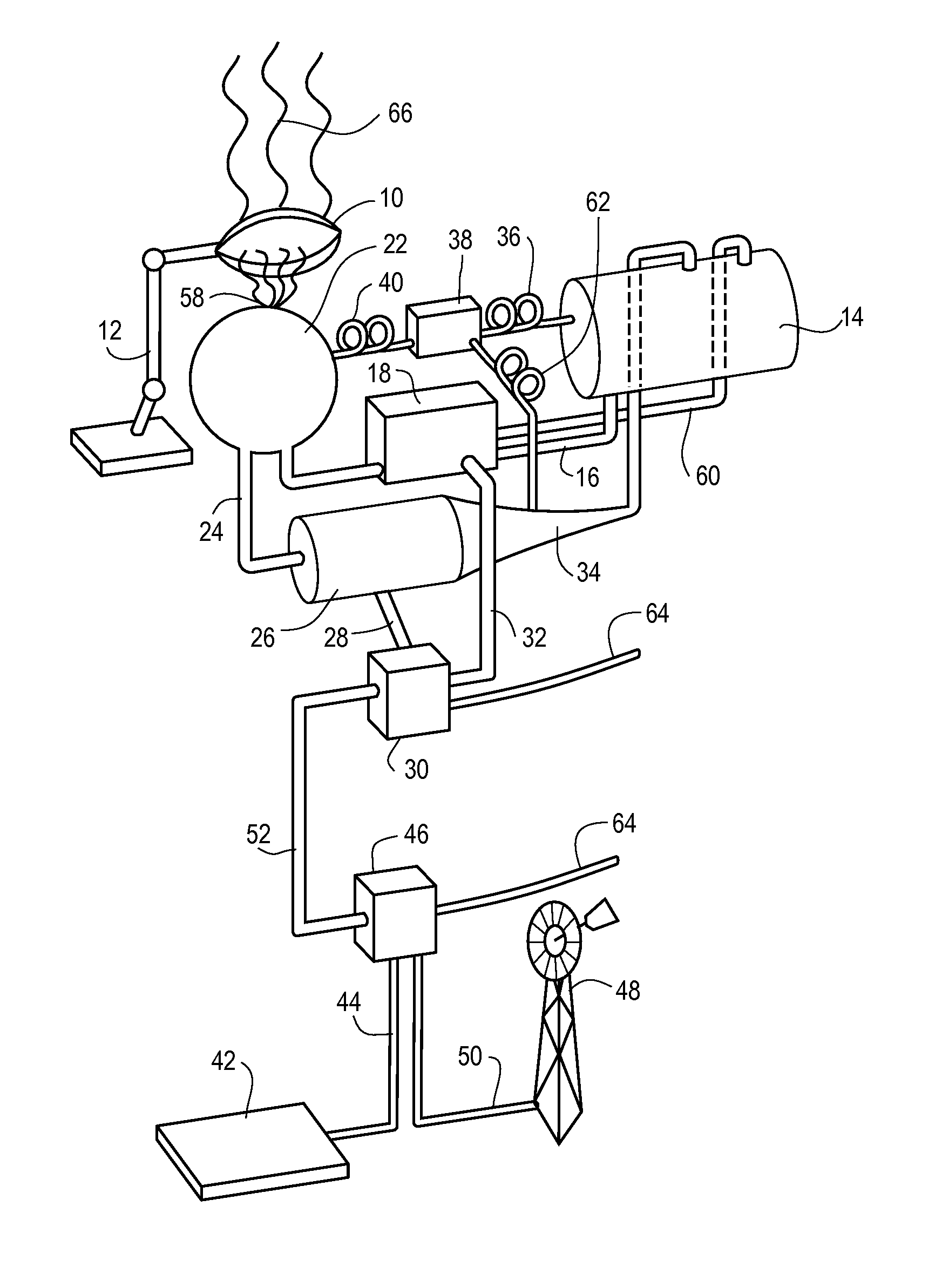
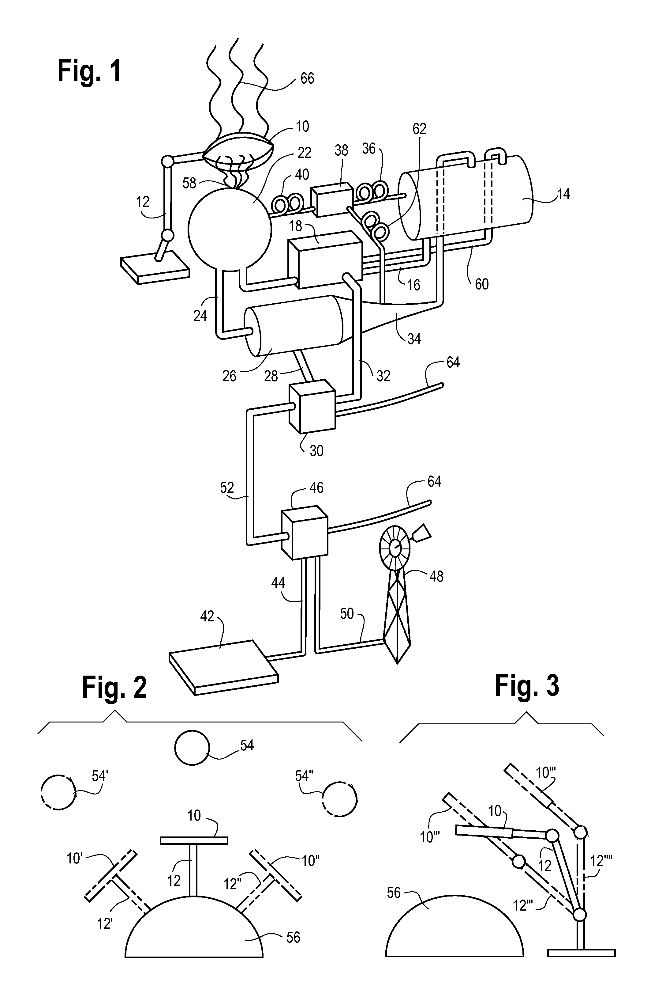
[0037]With reference to the drawings, specifically FIG. 1, a solar energy plant 11 will be described. The solar energy plant 11 utilizes the advancements previously mentioned.

[0038]The solar energy plant 11 is provided with a lens 10 mounted on a support 12. The lens 10 can be made of plastic or glass. In one preferred embodiment, preferred lens 10 would be substantially 5 (five) feet in diameter, but a wide variety of alternate sized lenses would be acceptable. The lens 10 must focus light 66 from the sun 54 to a focal point 58. The distance between the focal point 58 and the lens 10 will depend on the size of the lens 10 and the type of lens 10. The lens 10 could be a convex lens, double convex lens, magnifying lens, or any other form of lens 10 structure and still be covered by the scope of this invention. As previously mentioned, the lens 10 could be a magnifying lens and thus magnify the light 66, to increase the intensity of the light 66 on the focal point 58.

[0039]The support...


PUM


Abstract

A power plant that uses a lens to focus solar energy onto a closed system loop is disclosed wherein a closed loop system is provided having a chamber that converts a liquid into a gas by absorbing heat. The heat being created has been generated by the focused solar energy. The gas drives a turbine engine, which, with the use of a generator, produces an electrical output. A heat exchange system also transfers heat energy to the chamber from the liquid storage tank and the capillary tube. The present invention may also communicate with traditional environmentally economic sources of power such as windmills and hydroelectric dams. Further, a method employing the same principals is disclosed.

Description

FIELD OF THE INVENTION[0001]The present invention relates to power plants that utilize solar energy in order to create electrical energy and more specifically, the disclosed invention relates to those power plants that focus the solar light through the use of a lens as well as situations wherein a power plant may continue to produce electrical energy when no source of solar light is present by means of a heat exchange and storage system.BACKGROUND OF THE INVENTION[0002]Energy concerns have long been the focus of many different groups. The world's attachment to fossil fuels has become a crutch. Additionally, fossil fuels exist in a limited amount and are thought to create serious environmental problems. The sun is an energy source that many scientists and inventors have thought of as a way to side step fossil fuels and their detrimental affects. However, very few people have been able to efficiently harness this energy source. Several patents have disclosed methods and structures for...

Claims


Application Information

Patent Timeline
Patent Type & Authority Patents(United States)
IPC IPC(8): B60K16/00
CPCF03G6/06Y02E10/46
Inventor CONNELLY, BRUCE
Owner CONNELLY BRUCE
Why Eureka
Try Eureka