Supercharge Your Innovation With Domain-Expert AI Agents!

Head piece for refueling systems

a refueling system and head piece technology, applied in the direction of liquid bottling, packaging goods, special packaging, etc., can solve the problems of high maintenance expenditure, high susceptibility of hoses, and associated difficulties in handling, so as to achieve low maintenance expenditure, low force expenditure, and easy operation

Active Publication Date: 2007-03-06
DABICO NETHERLANDS HLDG BV
View PDF9 Cites 3 Cited by
  • Summary
  • Abstract
  • Description
  • Claims
  • Application Information

AI Technical Summary

Benefits of technology

"The invention is a head piece for refueling and unrefueling systems that is easy to operate, requires low maintenance expenditures, and can be connected to a tank or vehicle quickly and safely. The head piece has a parallel lever drive that holds a refueling coupler in a certain position during adjustment, making it easier to align the coupler with the tank or vehicle. The head piece can be connected to a stationary or mobile system and is suitable for airplanes and other vehicles. The invention also includes an adjusting device for the first swivel joint and a balancing device to counterbalance the pipe sections and swivel joints. The technical effects of the invention are simplified and safe refueling and unrefueling systems that can be easily connected and disconnected."

Problems solved by technology

However, refueling systems known from the state of the art have the disadvantage that their handling is associated with significant difficulties.
For example, hoses represent a significant safety risk due to their susceptibility and sensitivity to heat, particularly when they are used in the vicinity of hot turbines and engines or in the vicinity of running turbines, respectively.
These disadvantages simultaneously require intensive maintenance and inspection activities that need to be carried out before, during and / or after each refueling process.
In addition, rigid head pieces or refueling systems known from the state of the art have the significant disadvantage of being very complicated to handle, wherein the connection with the tank connection piece of the vehicle or aircraft to be refueled is very difficult to produce and requires a high expenditure of force.
Particular problems arise when the tank connection piece of wide-body aircraft is situated on the underside of the wings.

Method used


Image

  • Head piece for refueling systems
  • Head piece for refueling systems
  • Head piece for refueling systems

Examples


Embodiment Construction

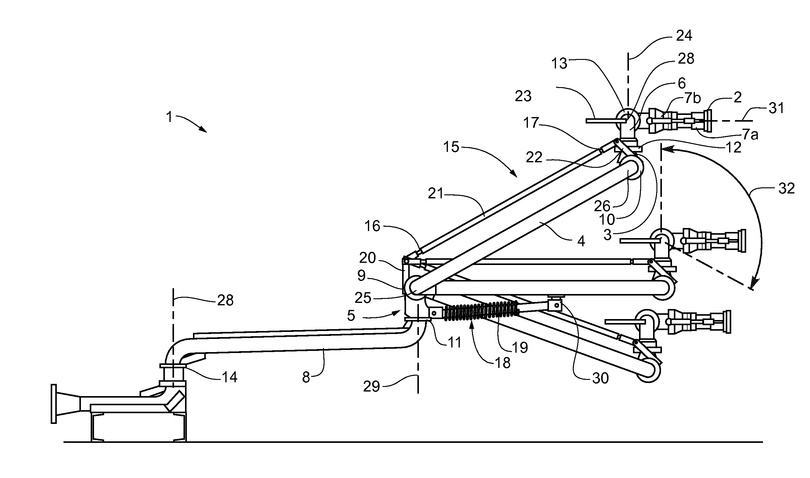
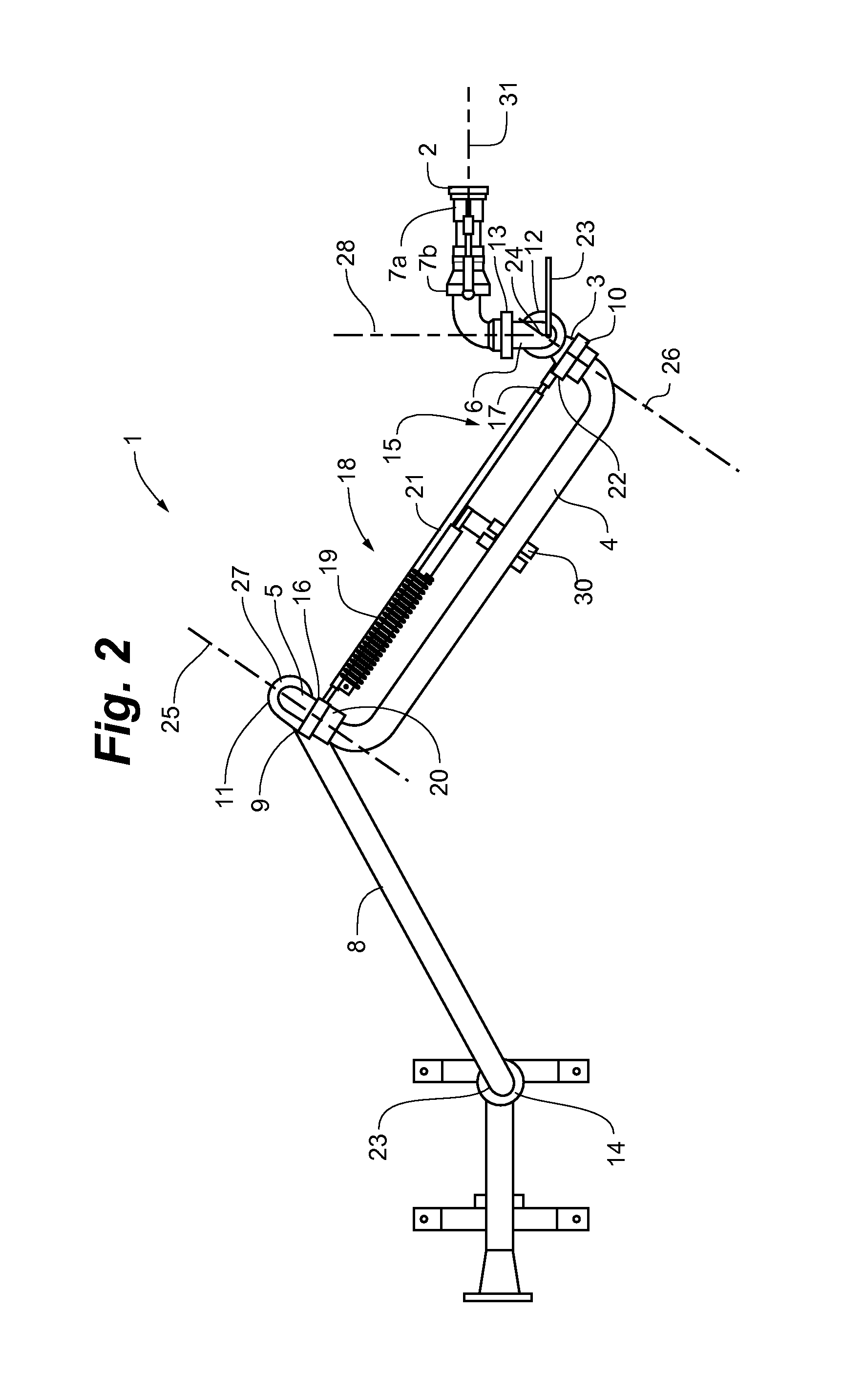
[0041]The head piece 01 shown in FIG. 1 consists of several swivel joints 09, 10, 11, 12, 13, 14 and several pipe sections 03, 04, 05, 06, 07 and 08 that are connected to the swivel joints. The fifth rigid pipe section 07 connects the fifth swivel joint 13 to a downstream refueling coupler 02. The fifth rigid pipe section 07 is also provided with a handle piece 23 that serves for maneuvering the head piece 01 and the refueling coupler 02, respectively.

[0042]The swivel joints 09, 10, 11, 12, 13 and 14 arranged on the head piece 01 make it possible to freely adjust and align the head piece 01, particularly the distance, the height and the angle of the refueling coupler 02. A balancing device 18 is provided on the head piece 01 in order to ensure a very exact adjustment of the head piece 01 and to simplify the insertion of the refueling coupler 02 into the tank of the vehicle or aircraft, respectively. This balancing device 18 essentially consists of a prestressed spring assembly 19 th...


PUM

PropertyMeasurementUnit
heightaaaaaaaaaa
lengthaaaaaaaaaa
horizontal distanceaaaaaaaaaa

Abstract

The invention pertains to a head piece (01) with a refueling coupler (02) for being connected to a tank, wherein several rigid pipe sections (03, 04, 05, 06, 07, 08) are provided for conveying the fuel, wherein the pipe sections (03, 04, 05, 06, 07, 08) are connected by means of several swivel joints (09, 10, 11, 12, 13, 14) in order to realize an adjustable spatial arrangement of the refueling coupler (02), and wherein at least a first swivel joint (09) and a second swivel joint (10) can be respectively swiveled about a horizontal swiveling axis (25, 26) in order to adjust the height of the refueling coupler (02). A parallel lever drive (15) is provided on the head piece (01) in order to hold a first pipe section (03) in a certain angular position during the height adjustment of the refueling coupler (02).

Description

CROSS REFERENCE TO RELATED APPLICATIONS[0001]The present Application claims the benefit of European Patent Application number 04016427.9 filed on Jul. 13, 2004. The entire disclosure of the above-mentioned patent application is hereby incorporated by reference herein.BACKGROUND OF THE INVENTION[0002]The invention pertains to a head piece for mobile or stationary refueling systems that comprises a refueling coupler for being connected to a tank, wherein several rigid pipe sections are provided for conveying the fuel.[0003]Head pieces of this type are used, for example, as refueling arms or loading arms in industrial plants, particularly in the chemical industry. Such head pieces are also used as refueling systems at airports, particularly for refueling military aircraft.[0004]When loading fuel and other liquid chemical mediums into tank trucks, railroad tank cars, non-stationary containers or aircraft, large quantities of the medium need to be transferred from a stationary or mobile ...

Claims


Application Information

Patent Timeline
Patent Type & Authority Patents(United States)
IPC IPC(8): B65B1/04B67D7/00B67D9/02
CPCB64F1/28F16L27/0861B67D7/42B67D7/002Y10T137/8807
Inventor VON MEYERINCK, WOLFGANG
Owner DABICO NETHERLANDS HLDG BV
Features
  • R&D
  • Intellectual Property
  • Life Sciences
  • Materials
  • Tech Scout
  • Unparalleled Data Quality
  • Higher Quality Content
  • 60% Fewer Hallucinations
Learn More