Central tire inflation system for drive axle

a drive axle and tire inflation technology, applied in the direction of tire measurement, vehicle components, transportation and packaging, etc., can solve the problems of large seals, difficult assembly, and difficult integration of cti systems for drive axles into conventional wheel ends, and achieve the effect of convenient installation

Active Publication Date: 2007-03-06
ARVINMERITOR TECH
View PDF46 Cites 42 Cited by
  • Summary
  • Abstract
  • Description
  • Claims
  • Application Information

AI Technical Summary

Benefits of technology

[0010]In one disclosed embodiment, the bore extends through the entire length of the wheel shaft from a first end face to a second end face. The air supply component includes a base portion that is mounted to non-rotating wheel structure and an air conduit that extends from the base portion and into the bore at the first end face. Preferably, the fluid inlet and fluid outlets are coaxial with the laterally extending bore. By forming the bore within the wheel shaft, air is easily supplied to the tire assembly for a driven wheel without interfering with the wheel bearings and without requiring passages to be drilled into the wheel hub itself.
[0011]In one disclosed embodiment, the subject invention is incorporated into an inverted portal drive axle. The inverted portal drive axle includes an input driven by a vehicle power source and defining a longitudinal axis. The input is operably coupled to a differential, which is in driving engagement with first and second axle shafts. In an inverted portal axle configuration, the input is positioned laterally closer to one wheel assembly than the other wheel assembly, thus, one of the first or second axle shafts is significantly longer than the other axle shaft. Each axle shaft drives a gear set that raises the driving input from a lower axle shaft level up to a higher wheel axis level. The gear sets drive the wheel shafts, which in turn drive the wheel hubs. In this axle configuration, the bore is coaxial with the wheel axis of rotation, which is parallel to and spaced apart from an axle shaft axis of rotation. The fluid inlets at the inboard ends of the wheel shafts are easily accessed through a non-rotating gearbox or axle housing. Thus, the air supply component can be easily installed to communicate with the wheel shaft bore without interfering with other wheel components and without requiring significant wheel modifications. A connector and hose assembly are operably coupled to each fluid outlet at the outboard end of the wheel shafts to conduct the air to the tire assemblies.

Problems solved by technology

Traditionally, CTI systems for drive axles have been more difficult to incorporate into conventional wheel ends.
This configuration requires large, expensive seals, is difficult to assemble, and is expensive to machine.
Further, wheel hubs for drive axles using disc brakes and single tires often do not have enough packaging space to accommodate drilled passageways.
Thus, using a CTI system for such a configuration is not practical.
Another disadvantage with CTI systems that utilize passageways formed within the wheel hub, is interference with wheel bearing operation.
Forming an air passageway through the hub can be detrimental to bearing operation, especially if one of the seals fails or leaks.
The air coupling is a complex mechanism requiring several component pieces and multiple seals, which makes the coupling very expensive.
Further, assembling the coupling onto the axle shaft is difficult and time consuming.
Also, the system is difficult to maintain and repair.

Method used


Image

  • Central tire inflation system for drive axle
  • Central tire inflation system for drive axle
  • Central tire inflation system for drive axle

Examples


Embodiment Construction

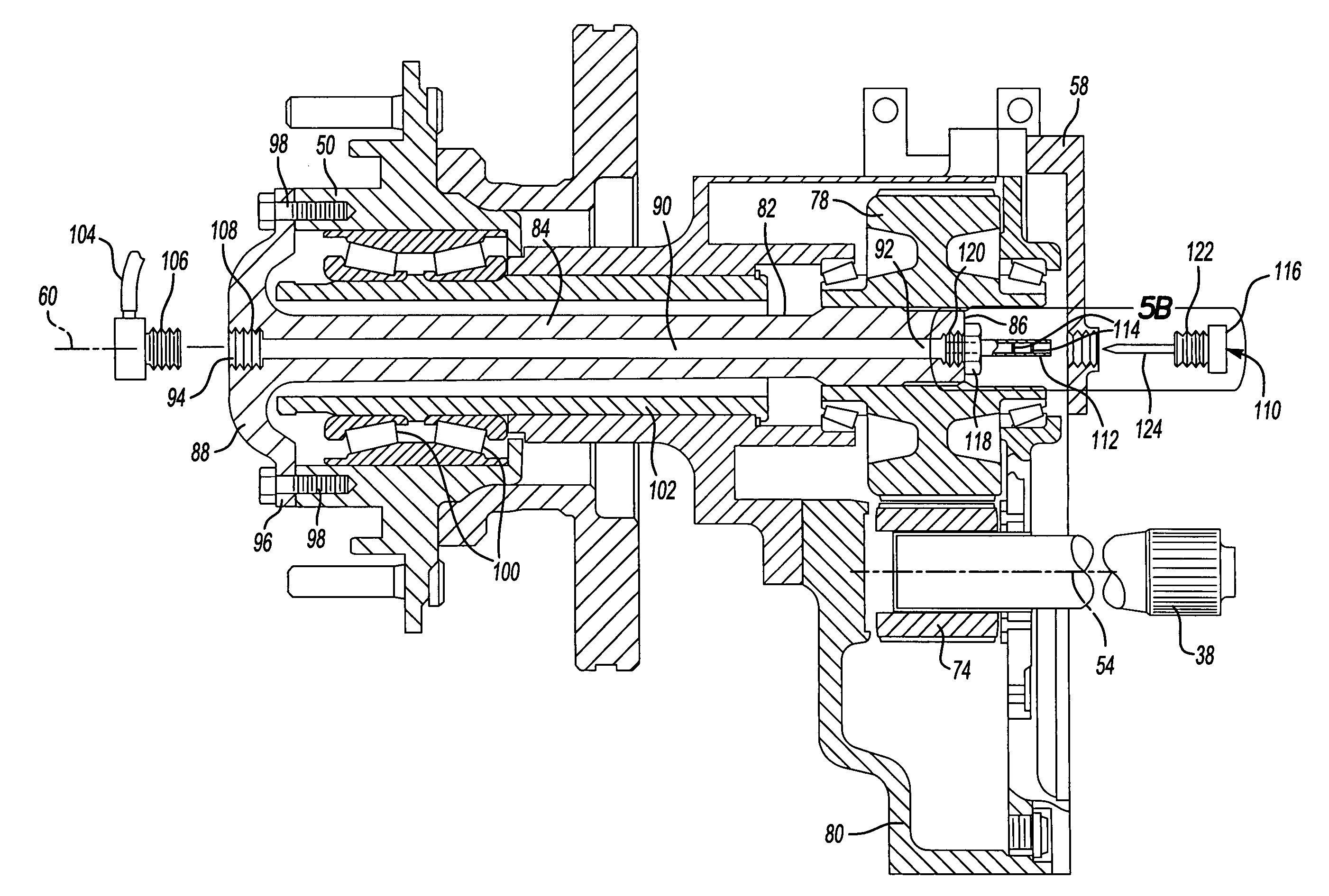
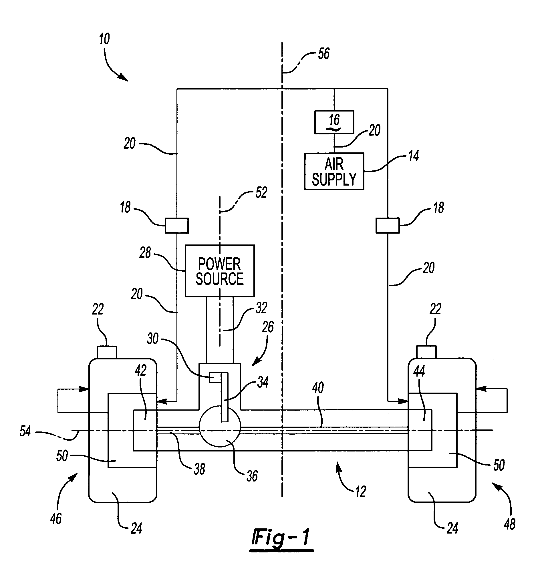
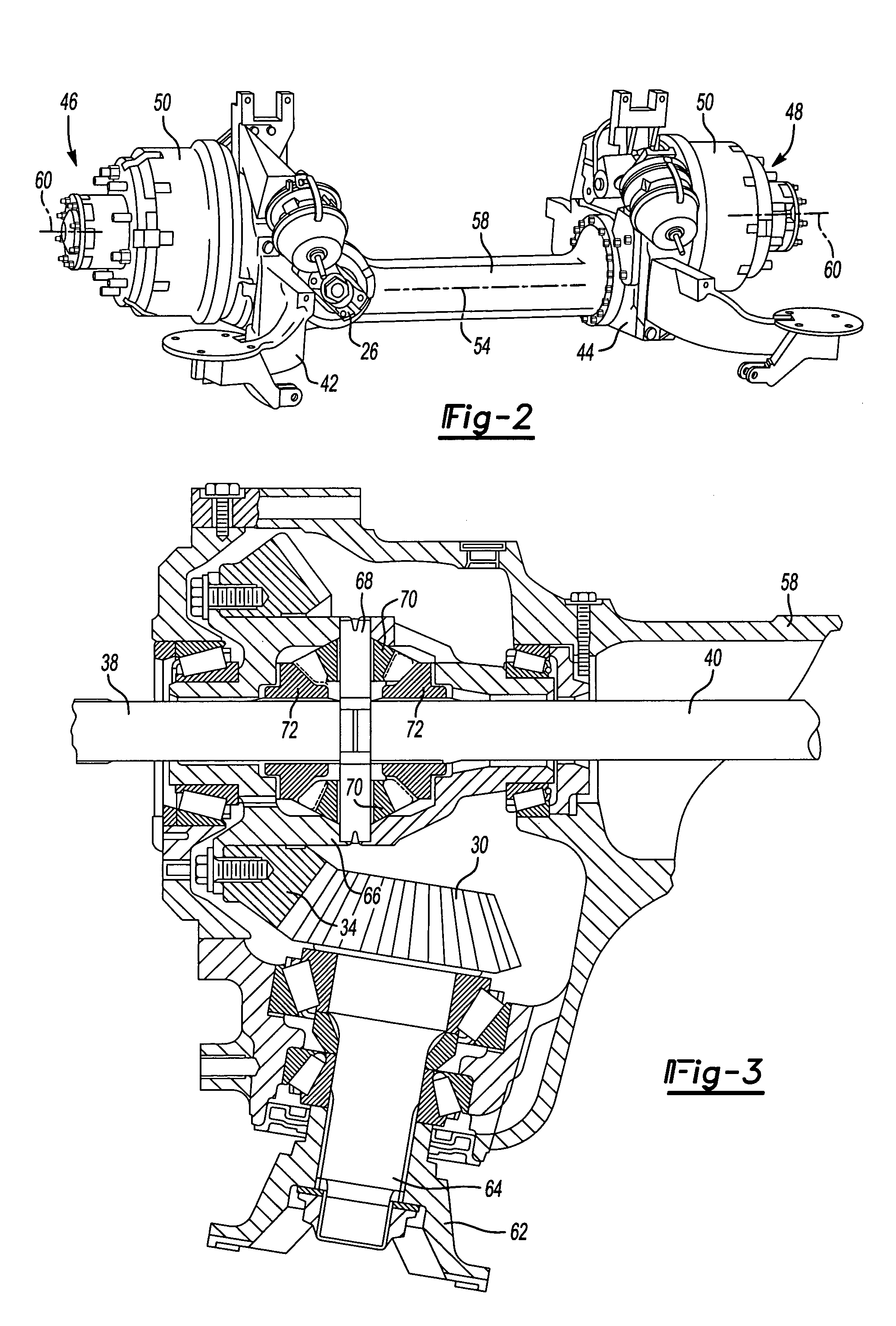
[0023]FIG. 1 shows a schematic view of a central tire inflation (CTI) system 10 incorporated into a drive axle assembly 12. Preferably, the drive axle assembly 12 is an inverted portal drive axle, however, the CTI system 10 could be used in portal drive axles, or other similar drive axles known in the art. The CTI system 10 includes an air supply 14 that is carried by a vehicle or a vehicle trailer. The air supply 14 can be an existing air supply tank on the vehicle, such as for a pneumatic braking system, for example, or can be a separate air supply dedicated to the CTI system 10.

[0024]The CTI system 10 also includes a plurality of pressure valves and sensors that are used to monitor tire pressure, air supply pressure, and to control air flow throughout the CTI system 10. In one example shown in FIG. 1, the CTI system 10 includes a pressure regulator and unloader valve assembly 16. The pressure regulator is typically set at a desired tire pressure level. The unloader valve is set a...


PUM


Abstract

A tire inflation system for a portal drive axle assembly includes fluid flow passages that are formed within rotating wheel shafts, which drive a pair of wheel end assemblies. The portal drive axle assembly includes a driving input that drives a pair of axle shafts. A wheel gear assembly operably couples each axle shaft to the respective wheel shaft. The wheel gear assemblies transfer the driving force from the axle shafts to the wheel shafts, which are positioned at different vertical location relative to the axle shafts. A first end of each wheel shaft is in fluid communication with a vehicle air supply and a second end of each wheel shaft is in fluid communication with a tire assembly. Seal assemblies are mounted for rotation with the wheel shaft at the first end of the wheel shafts. An air supply needle is mounted to a non-rotating axle structure and includes a base member that is in fluid communication with the air supply and a hollow needle body that extends from the base member through the seal assembly and into the fluid flow passage. Thus, air is selectively supplied to the tire assemblies in a sealed environment by traveling from the air supply, through the rotating wheel shafts, and into the tire assemblies.

Description

BACKGROUND OF THE INVENTION[0001]The subject invention relates to a central tire inflation (CTI) system that utilizes passages formed within rotating wheel shafts to provide an easily sealed flow path to conduct air from a vehicle air supply to a tire assembly on a drive axle. The passage in each wheel shaft includes a fluid inlet formed at an inboard shaft end that communicates with the air supply and a fluid outlet formed at an outboard shaft end that communicates with the tire assembly.[0002]CTI systems automatically supply air to vehicle tires when certain predetermined conditions are met. In a typical situation, the CTI system will automatically add air to a tire that becomes under-inflated during vehicle operation. CTI systems typically include sensors and pressure regulators for monitoring the pressure in each of the vehicle's tires. When pressure in any tire drops below a predetermined level, the system automatically supplies air to that tire until a desired tire pressure is...

Claims


Application Information

Patent Timeline
Patent Type & Authority Patents(United States)
IPC IPC(8): B60C23/00
CPCB60C23/003B60C23/00318B60C23/00336B60C23/00354B60C23/00363B60C23/0039
Inventor HAYES, BRIAN D.BRILL, LAWRENCE D.
Owner ARVINMERITOR TECH
Why Eureka
Try Eureka