Welder with light source

Inactive Publication Date: 2007-03-06
FISHER CARL M
View PDF16 Cites 23 Cited by
  • Summary
  • Abstract
  • Description
  • Claims
  • Application Information

AI Technical Summary

Benefits of technology

[0006]In a welder wand including a welding tip attached to handle with an elongate, rigid conduit, the handle having a trigger for activating the welding tip, improvements therein according to the invention include an optical light system attached to the welder wand consisting of a light source mounted proximate to the welding tip and a switch mounted proximate to the handle. The switch is operatively coupled to the light source for selectively activating and deactivating the light source, whereby the light source produces and directs light at the welding tip when activated by the switch. An articulating arm couples the

Problems solved by technology

The coated electrode is used less than the consumable electrode because of its lower productivity.
In any case, the energy source and/or the ignited gas both generate a tremendous amount of light which can damage the eyes of an operator using the welder.
Unfortunately, the window also blocks out visible light so that the ope

Method used


Image

  • Welder with light source
  • Welder with light source
  • Welder with light source

Examples


Embodiment Construction

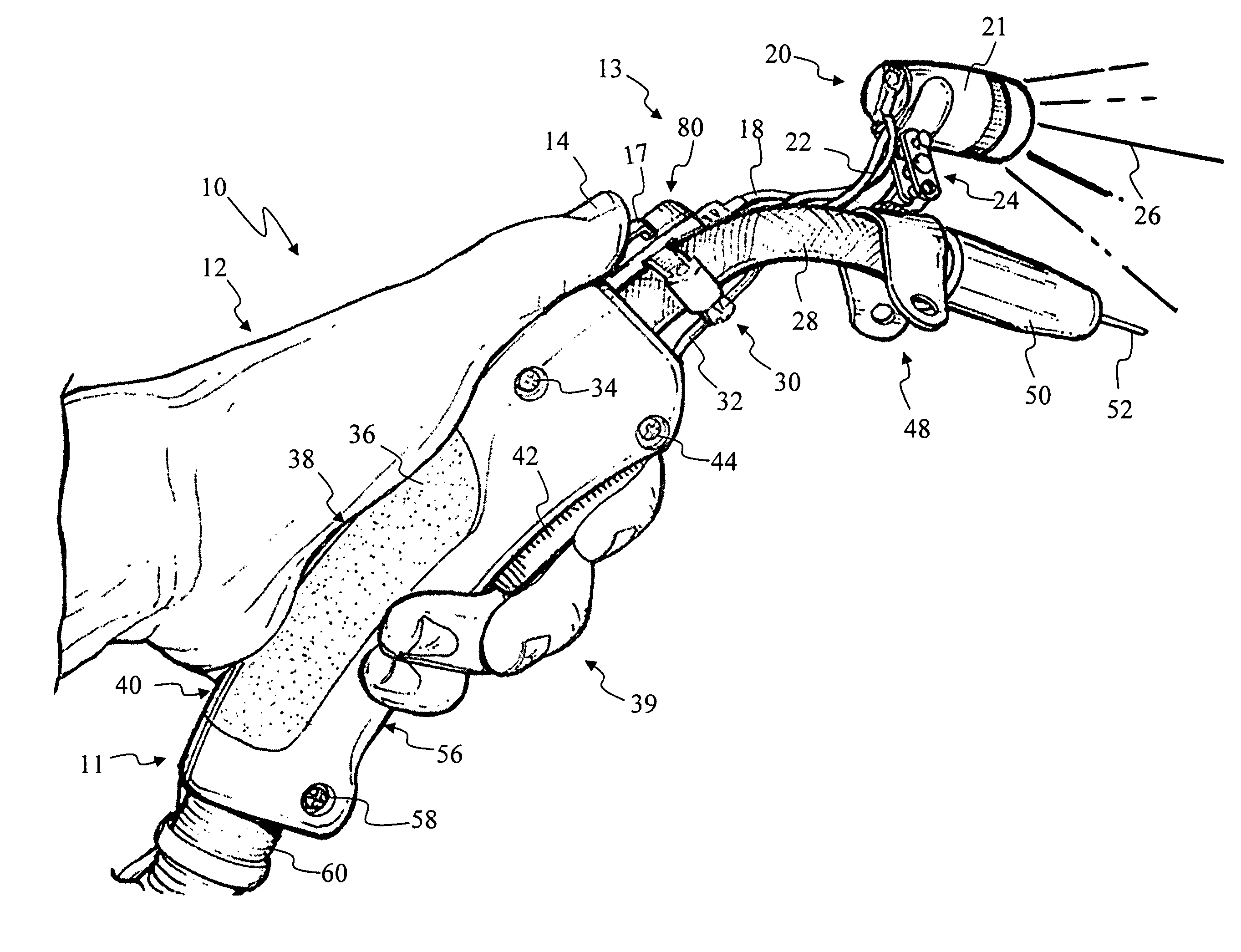
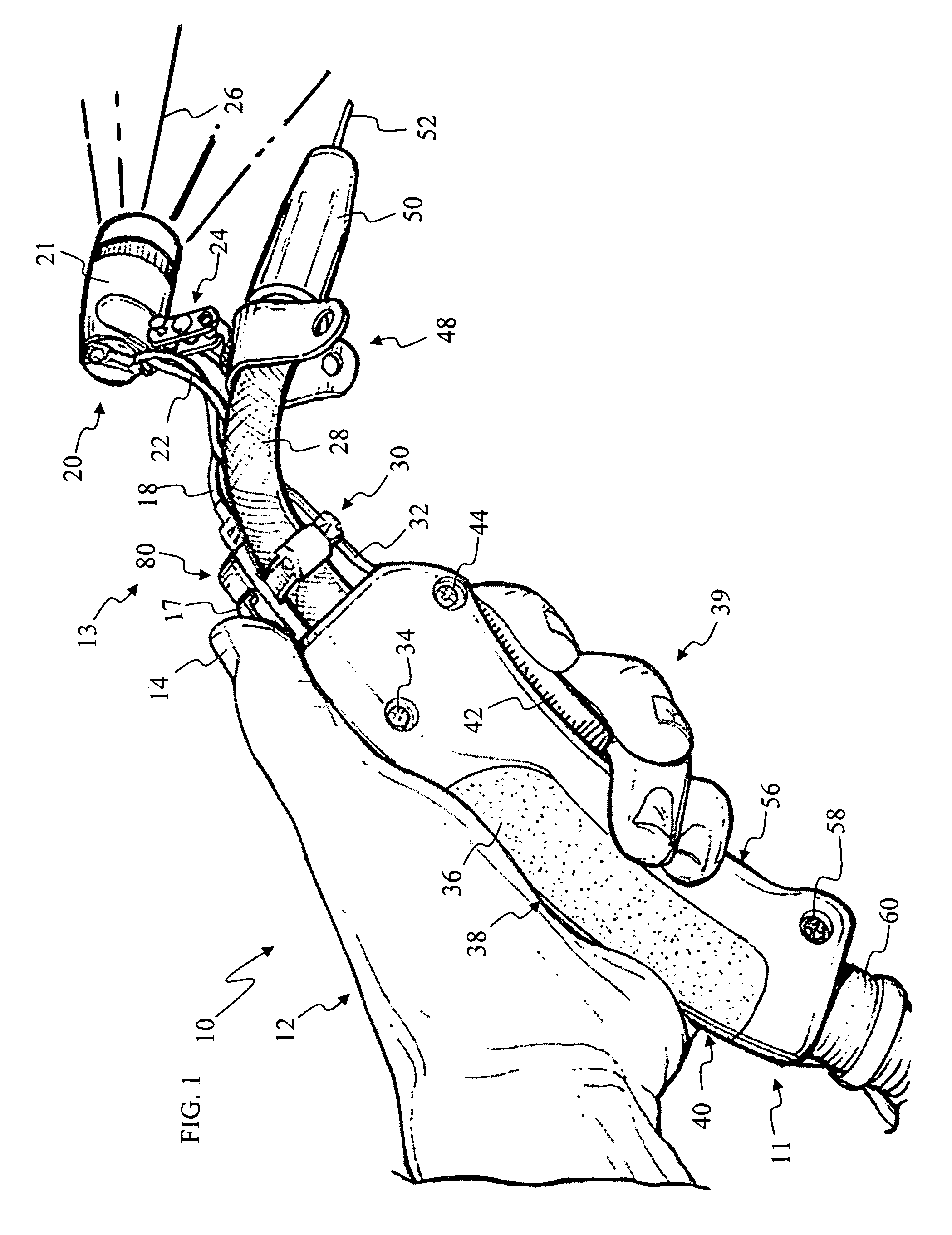
[0018]Turning now to the drawings, in which like reference characters indicate corresponding elements throughout the several views, attention is first directed to FIG. 1 in which there is seen a perspective view of a welder wand 10 incorporating an optical light system 13 in accordance with the principle of the invention. Welder wand 10 is well-known in the art, the specific details of which will readily occur to the skilled artisan and will be discussed only to the extent necessary to support the teachings of the present invention, which consist of improvements therein, namely, the provision of optical light system 13.

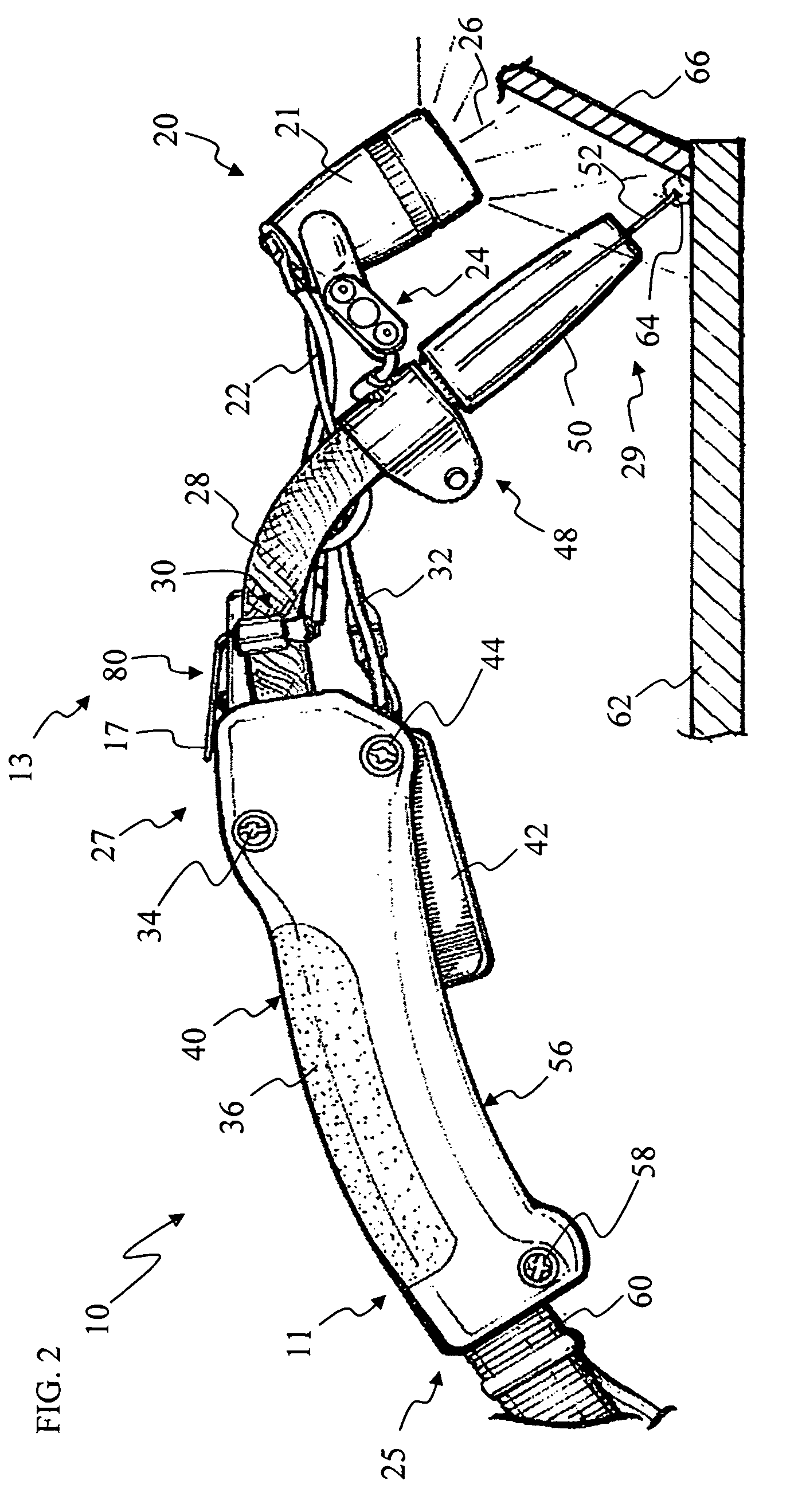
[0019]With continuing regard to FIG. 1, and also to FIG. 2, welder wand 10 includes a rigid conduit 28 in which a gas flows therethrough. The gas that passes through conduit 28 is a type typically used in welding, such as oxygen, argon, acetylene, etc., and can include carbon. In this particular example, welder wand 10 is a MIG welder wand forming part of a MIG welder...


PUM


Abstract

In a welder wand including a welding tip attached to handle with an elongate, rigid conduit, the handle having a trigger for activating the welding tip, improvements therein including an optical light system attached to the welder wand comprising a light source mounted proximate to the welding tip and a switch mounted proximate to the handle, the switch operatively coupled to the light source for selectively activating and deactivating the light source, whereby the light source produces and directs light at the welding tip when activated by the switch.

Description

CROSS REFERENCE TO RELATED APPLICATION[0001]This application claims the benefit of U.S. Provisional Application No. 60 / 691,817, filed Jun. 17, 2005.FIELD OF THE INVENTION[0002]The present invention relates to welders and, more particularly, to a welder with a light source.BACKGROUND OF THE INVENTION[0003]There are many different types of welders used to fuse pieces of metal together. The different types of welders are generally put into two categories which depend on the energy source employed. One category of welders uses an energy source within the work pieces to be welded together. These types of welders include electric resistance welding, friction welding, diffusion welding, explosive welding, and ultrasonic welding. The other category of welders uses an external energy source, such as a flame, an electric arc, an electron beam, a laser beam, or a plasma jet. This second category is the most widely used in industry, except the automotive industry, where resistance welding is ty...

Claims


Application Information

Patent Timeline
IPC IPC(8): B23K9/32
CPCB23K9/32
Inventor FISHER, CARL M.
Owner FISHER CARL M
Why Eureka
Try Eureka