Peak power and speckle contrast reduction for a single layer pulse

a single-layer pulse and speckle contrast technology, applied in the field of optical imaging, can solve the problems of affecting the quality of optical systems, so as to and reduce the speckle contrast

Inactive Publication Date: 2007-03-06
KLA TENCOR TECH CORP
View PDF20 Cites 23 Cited by
  • Summary
  • Abstract
  • Description
  • Claims
  • Application Information

AI Technical Summary

Benefits of technology

[0015]The present invention is a system and method for reducing the peak power of a laser pulse. The system and method disclosed herein utilize multiple paths using a unique design to divide a pulse received from a light generating device, such as a laser, into multiple lower energy pulses, and delay those pulses such that they may strike the target surface at different times. The design provided herein comprises a plurality of beamsplitters combined with a plurality of delay elements to delay a pulse or pulses transmitted from the light emitting device in an advantageous manner. The design provides the ability to readily divide the pulse into two, four, eight, or conceivably any number of components with components delayed relative to one another. The energy in each pulse can be adjusted using a variety of optical attenuation schemes to produce pulses with substantially uniform energies. Energy received from the light generating device may be split into components using beamsplitters and directed through different paths toward the target, such as a semiconductor wafer surface. Certain optical delay arrangements using prisms, Brewster's angle surfaces, and reflecting devices employing mirrors or Total Internal Reflection (TIR) surfaces provide delay compensation for the optical paths. These delay schemes can be in classical arrangements such as a White Cell or Herriott Cell or other novel delay schemes described herein.
[0017]An alternate embodiment for reducing speckle contrast is disclosed wherein a single pulse is passed in an angular orientation through a grating to create a delayed portion of the pulse relative to the leading edge of the pulse. One side of the pulse is delayed with respect to the other side of the pulse. If this time delay is suitably longer than the coherence length of the laser pulse, multiple zones are created across the pulse that will not interfere. Each of these zones can then pass through a diffuser at different angles and the speckle contrast can be reduced. A second grating can also be used in combination with the first grating to remove the spectral dispersion while maintaining the optical delay from one side of the pulse to the other.
[0018]In addition, these techniques to reduce the speckle contrast can be used in combination with other speckle reduction techniques to further reduce the speckle. Two examples of such techniques are a light pipe and a lens array. A light pipe or lens array spatially divides an input beam into multiple beamlets. Each of these beamlets then overlaps at the output of the light pipe or lens array. If the spatial or temporal coherence of the input pulse is sufficient so that one beamlet does not interfere with another, speckle contrast can be reduced.
[0019]Further, the method described herein for creating multiple pulses from a single pulse effectively increases the repetition rate of a repetitively pulsed source. The method described herein for reducing the speckle contrast from a single pulse using a grating to delay one side of a pulse with respect to the other side effectively increases the pulse length in time. Using both of these techniques in combination may produce a continuous or nearly continuous source from a high repetition rate source.

Problems solved by technology

Pulsed illumination typically suffers from two major problems.
First, the peak power of the illumination transmitted from the illumination source can be very high and potentially damage elements in the optical system or the object being inspected.
Second, the light energy can suffer from “speckle” or random intensity distribution of light due to interference effects.
Further, instances occur wherein a higher repetition rate source is not available.
Several drawbacks exist for this approach.
First, the pulse-to-pulse uniformity is highly dependent on the quality of the mirror and beamsplitter used to form the multiple pulses as well as losses in the optical delay schemes.
Another limitation of the Horton design is that it is not well suited for the DUV-VUV spectral range.
Reflective coatings are much less efficient in this range and can cause large losses.
These losses will contribute to pulse-to-pulse nonuniformity and a reduction in the efficiency of the peak power reduction scheme.
An additional limitation of the Horton design is that it uses a single mirror and beamsplitter to generate the multiple pulses.
This optical setup is not flexible and inhibits compensation of different losses for each delay path.
In addition, this scheme offers no solution for dealing with the effects of speckle.
Also, losses from diffusers are typically very high.
In addition, rotating diffusers can be a source of vibration that can effect the image quality of the system.
This technique has several limitations including large size and very high cost.
In addition, electro optic modulators operating at high bandwidths in the DUV and VUV ranges are not available.

Method used


Image

  • Peak power and speckle contrast reduction for a single layer pulse
  • Peak power and speckle contrast reduction for a single layer pulse
  • Peak power and speckle contrast reduction for a single layer pulse

Examples


Embodiment Construction

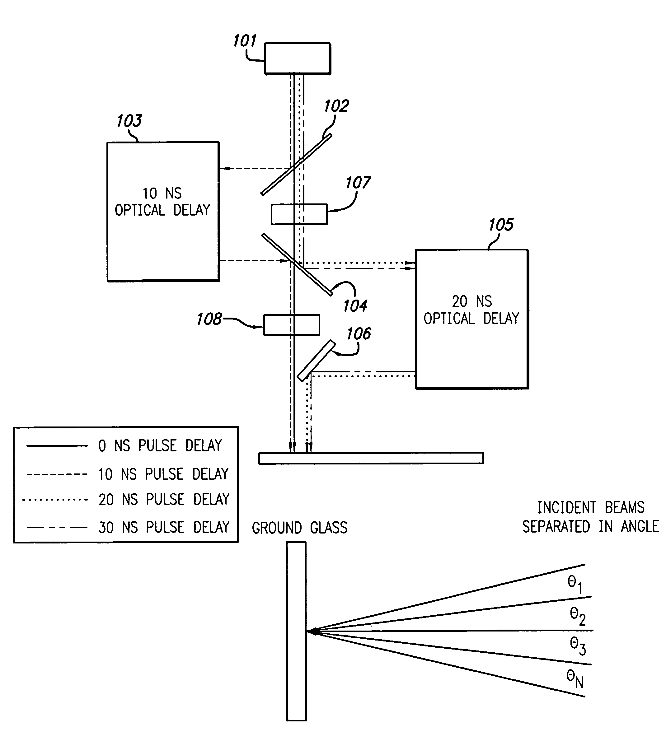
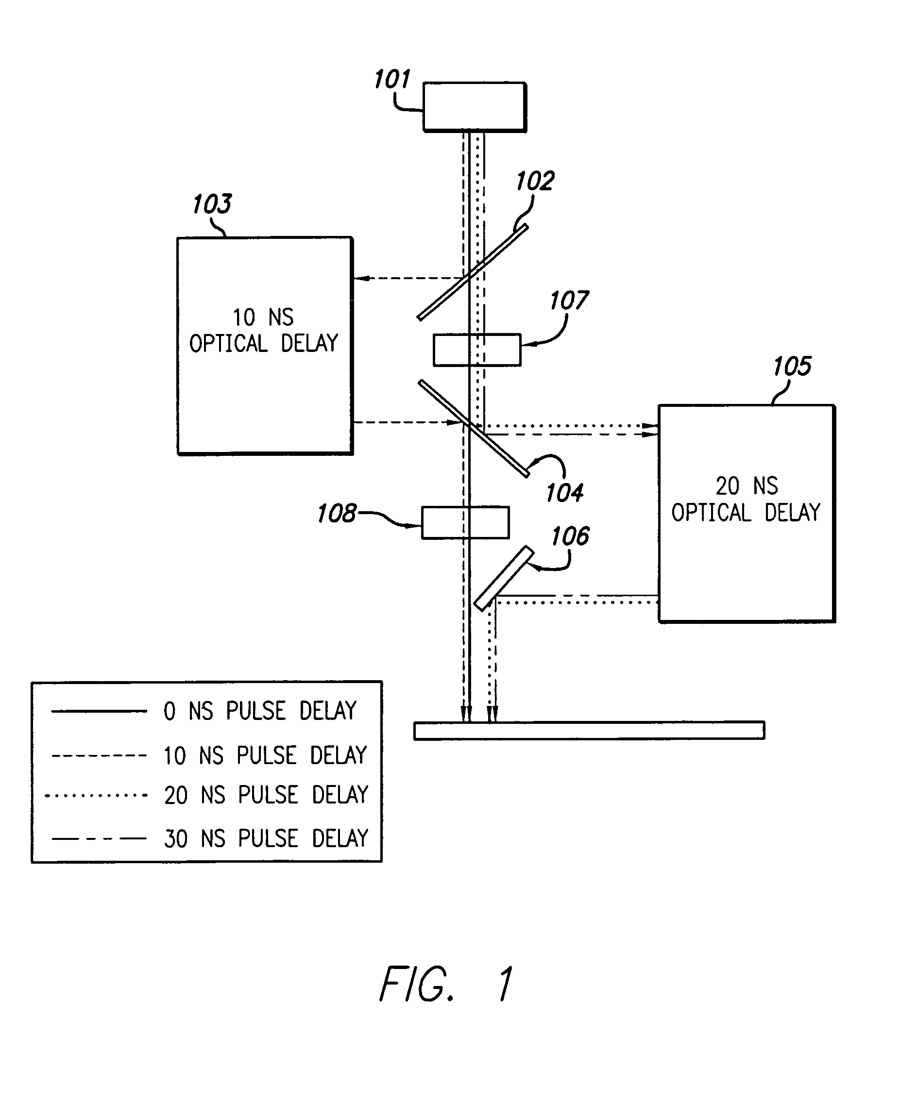
[0034]The present invention is a system and method for reducing peak power and speckle contrast in an imaging system employing a pulsed illumination source. The system uses multiple beam splitters in an arrangement that has the ability in many environments to minimize the energy variation between pulses. This system allows for a flexible setup where various combinations of plate beamsplitters and cube beamsplitters in different arrangements and geometries may be used while still within the scope of the teachings of the current invention.

[0035]In typical pulsed illumination source inspection systems, optical delay lines can be a major source of losses. The losses in the delay arms result from imperfect optics such as mirrors having less than 100% reflectivity, beamsplitters with loss and unequal beamsplit ratios, absorption of light energy in glass materials and coatings, and light energy scattering effects. These optical delay line losses adversely contribute to variations in the pu...


PUM


Abstract

A system and method for reducing peak power of a laser pulse and reducing speckle contrast of a single pulse comprises a plurality of elements oriented to split and delay a pulse or pulses transmitted from a light emitting device. The design provides the ability to divide the pulse into multiple pulses by delaying the components relative to one another. Reduction of speckle contrast entails using the same or similar components to the power reduction design, reoriented to orient received energy wherein angles between the optical paths are altered such that the split or divided light energy components strike the target at different angles or different positions. An alternate embodiment for reducing speckle contrast is disclosed wherein a single pulse is passed in an angular orientation through a grating to create a delayed portion of the pulse relative to the leading edge of the pulse.

Description

BACKGROUND OF THE INVENTION[0001]1. Field of the Invention[0002]The present invention relates generally to the field of optical imaging and more particularly to reduction of the peak power and speckle contrast for bright field and dark field inspection applications.[0003]2. Description of the Related Art[0004]Many optical systems are designed to produce images such as an inspection system for a partially fabricated integrated circuit or a photomask. Techniques and apparatus for inspecting circuits or photomasks are well known in the art and are embodied in various commercial products such as many of those available from KLA-Tencor Corporation of San Jose, Calif. Most optical imaging systems use a continuous illumination source. However, many times pulsed illumination sources are preferred or are the only sources available. This is especially true in the DUV spectral region below 250 nm where very few high brightness illumination sources exist that are not pulsed. Common examples are...

Claims


Application Information

Patent Timeline
Patent Type & Authority Patents(United States)
IPC IPC(8): G02B27/10G02B27/14G02B27/48H01S3/00H01S3/225
CPCG02B27/106G02B27/144G02B27/145G03F7/70583H01S3/005G02B27/48Y10S372/70H01S3/225
Inventor CHUANG, YUNG-HOARMSTRONG, J. JOSEPH
Owner KLA TENCOR TECH CORP
Why Eureka
Try Eureka