Laser drilling machining method

A laser perforation and processing method technology, applied in laser welding equipment, metal processing equipment, manufacturing tools, etc., can solve the problems of step-by-step perforation affecting perforation efficiency, prone to explosion, and disproportionate increase in perforation time, etc. The generation of laser-induced plasma, the improvement of perforation efficiency and stability, and the effect of reducing laser power

Inactive Publication Date: 2016-11-16
CHANGSHA UNIVERSITY OF SCIENCE AND TECHNOLOGY
View PDF9 Cites 11 Cited by
  • Summary
  • Abstract
  • Description
  • Claims
  • Application Information

AI Technical Summary

Problems solved by technology

At present, in actual production, the main problems in the laser cutting thick plate perforation process are: (1) prone to blast holes (no perforation, slag accumulates in the orifice), which damages the nozzle; (2) the perforation time is too long, As the plate thickness increases, the piercing time increases disproportionately, which affects production efficiency
[0004] The invention patent published on July 1, 2015, the authorized announcement number is "CN 102756214 B", and the invention title is "a laser perforation processing method" discloses a laser perforation process, which solves the problem of low perforation efficiency. problems, but the technical solution still has the following problems: the method proposes to match the laser parameters with high duty cycle and low frequency, it is difficult to optimize the matching in actual processing, and the high duty cycle can easily lead to hole blasting
[0005] The invention patent published on November 18, 2015, the authorized announcement number is "CN 103962734 B", and the invention title is "laser cutting fast zoom perforation method" discloses a laser cutting fast zoom mechanism and fast zoom perforation method. It solves the problem that the spatter sticks to the focusing lens and is prone to blast holes during the perforation process, but the technical solution still has the following problems: This method proposes to obtain reflective lenses with different surface curvature radii by changing the pressure, so as to obtain different focal depths. The laser beam realizes step-by-step perforation; however, the deformation response accuracy of the reflective mirror made of elastic material directly affects the focus position, which has a great impact on the perforation quality, and the step-by-step perforation seriously affects the perforation efficiency
[0006] The invention patent published on March 28, 2000 with the publication number "JP 2000-084686 A" and the invention name "Laser perforation, laser processing nozzle and laser cutting equipment" discloses a laser perforation method, which solves the problem of The problem of fast perforation on thick plates, but this technical solution still has the following problems: In this method, anti-splash oil is used to spread the perforated plate surface and nozzles. If the anti-splash oil flows into the laser perforation area, it will affect the stability of the perforation process. , while increasing the auxiliary process

Method used


Image

  • Laser drilling machining method
  • Laser drilling machining method
  • Laser drilling machining method

Examples


specific Embodiment approach 1

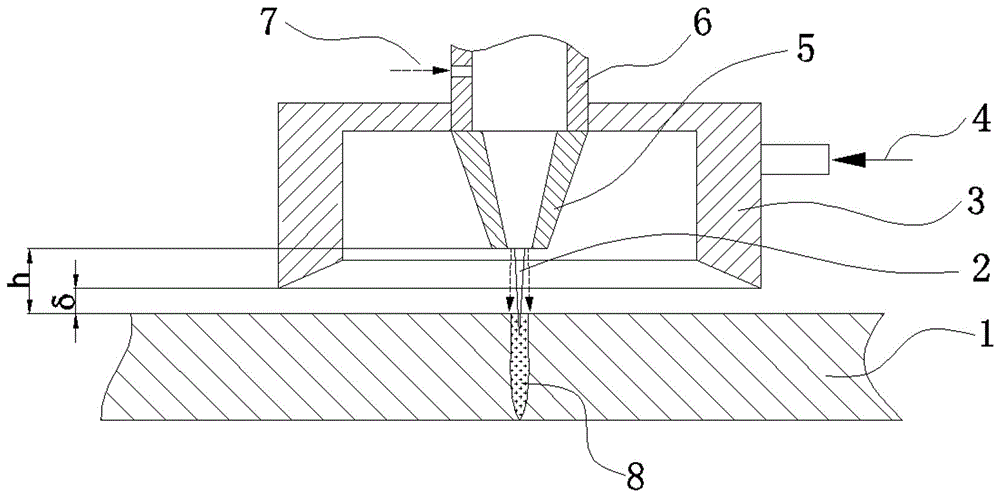
[0033] Such as figure 1 As shown, the workpiece to be cut is a carbon steel plate with a thickness of 20 mm to 35 mm. The vacuum cover installed on the cutting head forms a partial vacuum environment in the laser cutting perforation area. During the laser perforation process, the material has a strong melting ability, and the vapor pressure of the metal vapor in the perforation small hole is low, which avoids the formation of a large amount of molten metal sprayed upwards. Hole blasting realizes high-quality perforation processing.

[0034] In this embodiment, the laser drilling method includes the following steps.

[0035] Step 1: remove impurities on the upper surface of the workpiece 1 to be cut, and these impurities include water stains, oil stains, rust and other impurities that affect the welding quality.

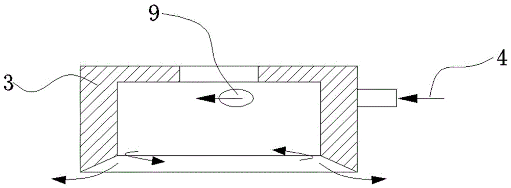
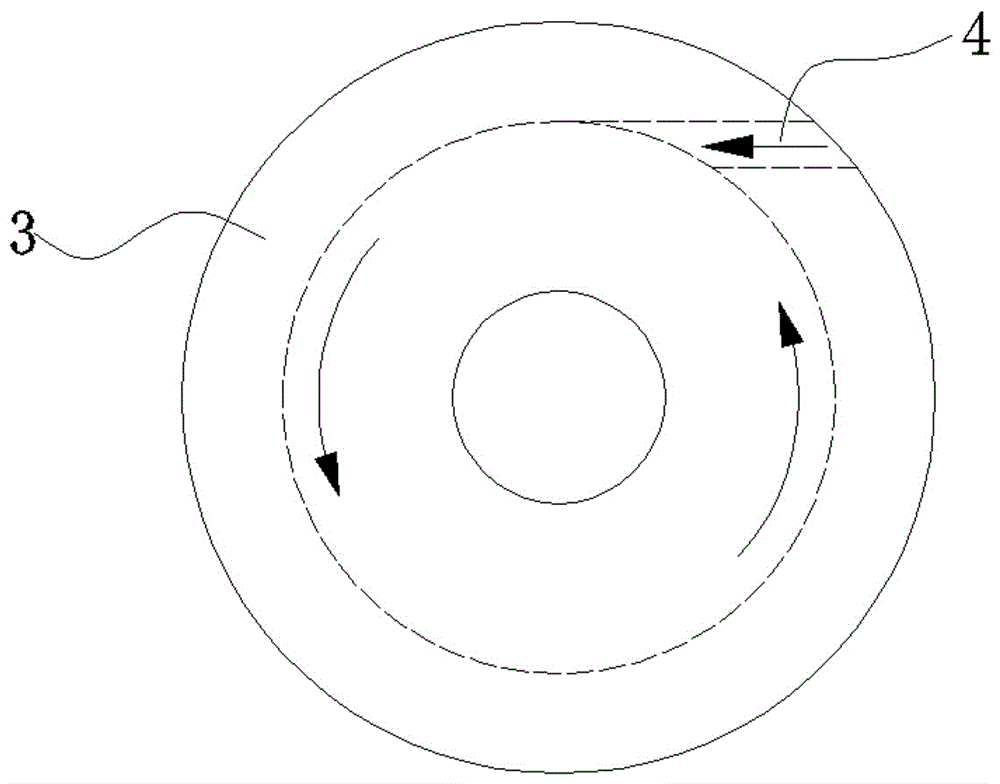
[0036] Step 2: Connect the cyclone vacuum cover 3 to the laser cutting head 6, the vacuum cover 3 can rotate on the laser cutting head 6, and the distance between t...

specific Embodiment approach 2

[0044] Such as figure 1 As shown, the workpiece to be cut is a stainless steel plate with a thickness of 15 mm to 25 mm. The vacuum cover installed on the cutting head forms a partial vacuum environment in the laser cutting perforation area. During the laser perforation process, the material has a strong melting ability, and the vapor pressure of the metal vapor in the perforation small hole is low, which avoids the formation of a large amount of molten metal sprayed upwards. Hole blasting realizes high-quality perforation processing.

[0045] In this embodiment, the laser drilling method includes the following steps.

[0046] Step 1: remove impurities on the upper surface of the workpiece 1 to be cut, and these impurities include water stains, oil stains, rust and other impurities that affect the welding quality.

[0047] Step 2: Connect the cyclone vacuum cover 3 to the laser cutting head 6, the vacuum cover 3 can rotate on the laser cutting head 6, and the distance between ...


PUM

PropertyMeasurementUnit
thicknessaaaaaaaaaa

Abstract

The invention relates to a laser drilling machining method. The laser drilling machining method comprises the following steps of step 1: preparing a workpiece (1) to be cut and removing impurities from the surface of the workpiece (1); step 2: connecting a vacuum hood (3) onto a laser cutting head (6), and enabling the distance from a cutting spray nozzle (5) and the the vacuum hood to the upper surface of the workpiece (1) to be adjustable; step 3: moving the laser cutting head above the workpiece, enabling the cutting spray nozzle to keep a certain distance from the surface of the workpiece and enabling the vacuum hood to keep a certain distance from the surface of the workpiece; setp 4: supplying dry compressed air from an air inlet port (4) of the vacuum hood; step 5: supplying drilling auxiliary gas from an auxiliary gas inlet port (7) of the laser cutting head; and step 6: starting a laser cutting system and enabling a laser beam (2) to radiate the upper surface of the workpiece vertically to complete the drilling process. According to the method, a partial vacuum environment is formed by the simple cyclonic-type vacuum hood, so that the problem can be avoided that large amounts of molten metal is injected upward and therefore a hole bursts, and the drilling efficiency and stability can be greatly improved.

Description

technical field [0001] The invention relates to the field of high-power laser cutting lasers, in particular to a perforation processing method for laser cutting medium and thick plates. Background technique [0002] In recent years, with the rapid development of the national economy, there is an increasing demand for efficient and high-quality cutting of thicker metal materials. At present, in industries such as shipbuilding, heavy machinery, large pressure vessels, large bridges and nuclear industry, there are problems of improving the cutting efficiency and quality of medium and thick steel plates, especially the steel used in the field of warships and submarines, because the steel used is relatively sensitive to heat input. The need to upgrade the existing thermal cutting technology is more urgent. [0003] Laser cutting accounts for more than 70% of the entire laser processing industry, and it is mostly used for high-precision cutting of thin plates. However, when the ...

Claims


Application Information

Patent Timeline
Patent Type & Authority Applications(China)
IPC IPC(8): B23K26/382B23K26/12
CPCB23K26/127B23K26/382
Inventor 张明军梁昶
Owner CHANGSHA UNIVERSITY OF SCIENCE AND TECHNOLOGY
Why Eureka
Try Eureka