
Laser cladding device and method for slender shaft-like workpieces

A technology of laser cladding and slender shafts, which is applied in the coating process of metal materials, coatings, etc., can solve the problems of reducing cladding deformation of slender workpieces, easy deformation of workpieces, and reducing heat input of workpieces

Inactive Publication Date: 2020-04-17
SHAANXI TIANYUAN MATERIALS PROTECTION TECH
View PDF5 Cites 11 Cited by
  • Summary
  • Abstract
  • Description
  • Claims
  • Application Information

AI Technical Summary

Problems solved by technology

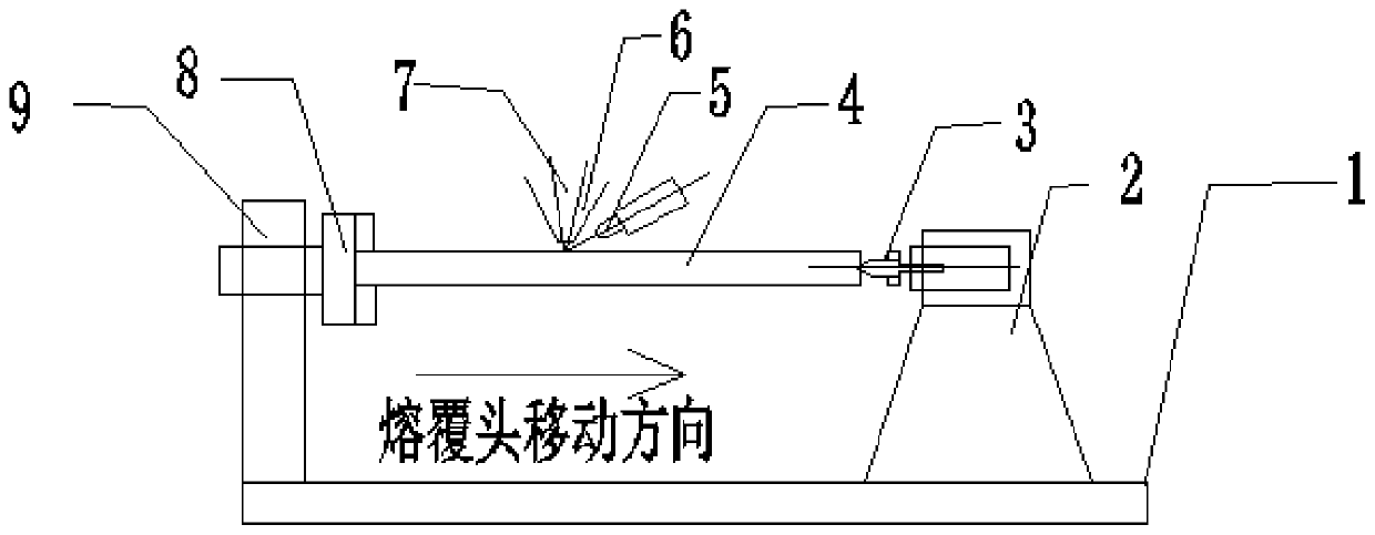
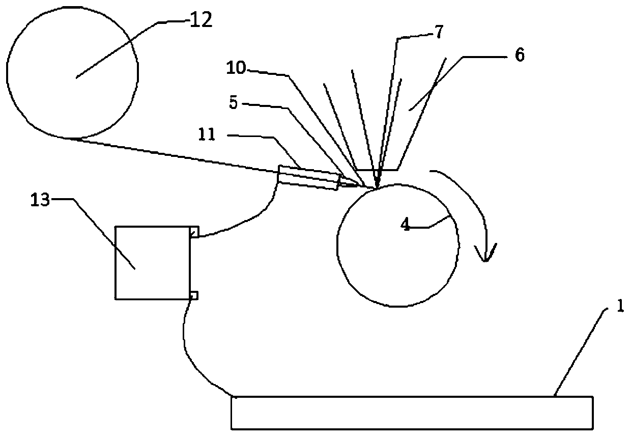
[0005] The object of the present invention is to propose a laser cladding device and laser cladding method for slender shaft workpieces, which solves the problem that the traditional laser cladding technology is easy to deform after cladding slender shaft workpieces. In the laser cladding treatment method for slender shaft workpieces: the innovative use of preheated wire laser cladding, the wire is preheated when it enters the molten pool, which effectively improves the absorption rate of the material to the laser, and can be used more than ordinary laser The cladding power is 50% lower than the laser power for wire cladding, which reduces the heat input of the workpiece; the innovative elastic tip is set at the tail of the cladding machine tool, and the maximum stroke of the elastic tip is 8mm-10mm, which can ensure that the cladding process When the workpiece is heated and expanded, it can expand and contract in the axial direction, avoiding deformation caused by excessive thermal expansion stress of the workpiece; the innovative cladding operation adopts segmented cladding technology, which effectively avoids excessive heat concentration and accumulation, and makes the laser cladding process The slender workpiece is dispersed by heat, which effectively reduces the cladding deformation of the slender workpiece

Method used


Image

  • Laser cladding device and method for slender shaft-like workpieces
  • Laser cladding device and method for slender shaft-like workpieces
  • Laser cladding device and method for slender shaft-like workpieces

Examples


Embodiment 1

[0062] 1) This embodiment is based on the above-mentioned method of the present invention for the surface metal wire laser cladding of the piston rod of the coal mine hydraulic support cylinder (hereinafter referred to as the piston rod). The standard diameter of the piston rod is φ90mm, and the size before cladding is φ89mm. The total length of the section is 1135mm, the diameter-to-length ratio of the piston rod is 7.8%, and the material is 27SiMn;

[0063] 2) The metal wire laser cladding scheme of the piston rod in this embodiment adopts a 4Kw fiber laser, the laser wavelength is 1064nm, and the spot size is φ3mm;

[0064] 3) The metal wire is stainless steel solid welding wire, material grade: TYG-005s, the cross-section shape of the wire is circular, and the diameter is φ1.2mm; the weight percentage of the main elements of the wire is: C≤0.20, Cr: 17.0-21.0 , Ni: 2.0-4.0, Mo≤1.50, P≤0.04, S≤0.03, Si≤1.50, Mn≤2.0, the rest is Fe;

[0065] 4) The dry elongation of the wel...

Embodiment 2

[0072] 1) This embodiment is based on the above-mentioned method of the present invention to carry out laser cladding on the surface of a corrosion-resistant guide shaft for a certain chemical equipment. The standard size of the workpiece to be clad is φ100mm, and the diameter of the workpiece before cladding is 99mm. The total length of the cladding area is 1500mm, the total length of the workpiece is 1630mm, and the material is 45# steel;

[0073] 2) In this embodiment, the cladding device is a 4Kw fiber laser, the laser wavelength is 1064nm, and the spot size is φ3mm;

[0074] 3) The metal wire is 316L stainless steel welding wire, the diameter of the welding wire is φ1.2mm; the weight percentage of each element in the wire material is: C≤0.04, Cr: 17.0-20.0, Ni: 11.0-14.0, Mo: 2.0-3.0, P ≤0.04, S≤0.03, Si≤1.00, Mn: 0.5-2.5;

[0075] 4) The length of the wire protruding from the wire guide nozzle is 15mm;

[0076] 5) Set the parameters of the wire cladding process as foll...

Embodiment 3

[0082] 1) This embodiment is based on the above-mentioned method of the present invention for the surface laser cladding of the coal mine hydraulic support cylinder piston rod (hereinafter referred to as the piston rod). The diameter of the piston rod is φ85mm, the size before cladding is φ84mm, and the total length of the cladding area is 735mm , the diameter-to-length ratio of the workpiece is 11.4%, and the material is 27SiMn;

[0083] 2) The metal wire laser cladding scheme of the piston rod in this embodiment adopts a 4Kw fiber laser, the laser wavelength is 1064nm, and the spot size is φ3mm;

[0084] 3) The metal wire is stainless steel solid welding wire, material grade: TYG-005s, the cross-section shape of the wire is circular, and the diameter is φ1.2mm; the weight percentage of the main elements of the wire is: C≤0.20, Cr: 17.0-21.0 , Ni: 2.0-4.0, Mo≤1.50, P≤0.04, S≤0.03, Si≤1.50, Mn≤2.0, the rest is Fe;

[0085] 4) The length of the wire protruding from the wire gu...


PUM

PropertyMeasurementUnit
lengthaaaaaaaaaa
lengthaaaaaaaaaa
shrinkageaaaaaaaaaa

Abstract

The invention provides a laser cladding device and method for slender shaft-like workpieces. The laser cladding is performed by preheating a wire, and the wire is preheated when entering a molten pool, so that the absorption rate of materials to laser is effectively improved; laser power 50% lower than that of ordinary laser cladding is used for wire cladding, so that the heat input of the workpieces is reduced; a movable center is arranged on the tail part of a cladding machine, and the maximum stroke of the movable center is 8mm, it is guaranteed that the workpieces can be expanded and contracted in the axial direction when the workpieces are thermally expanded in the cladding process, and deformation of the workpieces due to excessive stress caused by thermal expansion is avoided; and the segmented cladding technology is used in the cladding operation, excessive concentration and accumulation of heat is effectively avoided, the slender workpieces are dispersed by heat in the laser cladding process, and the cladding deformation of the slender workpieces is effectively reduced. According to the laser cladding device and method for the slender shaft-like workpieces, the applicationof laser cladding technology in the surface treatment process of slender shaft-like workpieces is promoted, and the broad prospect for popularization and application is achieved.

Description

technical field [0001] The invention belongs to the technical field of advanced manufacturing and remanufacturing, and in particular relates to a laser cladding device and a laser cladding method for slender shaft workpieces, especially a process method capable of preventing laser cladding deformation of slender shaft workpieces . Background technique [0002] As an advanced surface forming manufacturing technology, laser cladding technology has been widely used in recent years, especially in the surface replacement electroplating and remanufacturing repair solutions of shaft parts, such as hydraulic support cylinders , Laser cladding remanufacturing repair of piston rods, laser cladding remanufacturing repair of shaft parts in steel mills, etc. [0003] The application of laser cladding technology in the repair of medium and large shaft parts (such as hydraulic cylinders and piston rods for coal mines) has been very mature, but for small diameter (φ60-φ150mm) slender rods ...

Claims


Application Information

Patent Timeline
Patent Type & Authority Applications(China)
IPC IPC(8): C23C24/10C22C38/02C22C38/04C22C38/44C22C38/58
CPCC22C38/02C22C38/04C22C38/44C22C38/58C23C24/103
Inventor 曹鹏苏成明李建勋张毅王卓张飘飘赵俊霖王春昌
Owner SHAANXI TIANYUAN MATERIALS PROTECTION TECH
Learn More