Laser joining apparatus and laser joining method

A joining device and joining method technology, applied in the direction of laser welding equipment, auxiliary equipment, welding/welding/cutting items, etc., can solve the problems of decomposition, swelling, heat resistance temperature, low mechanical strength, etc., and achieve the reduction of material limitations, Product cost reduction, effect of laser power reduction

Inactive Publication Date: 2015-10-07
HITACHI LTD
View PDF6 Cites 11 Cited by
  • Summary
  • Abstract
  • Description
  • Claims
  • Application Information

AI Technical Summary

Problems solved by technology

However, thermoplastic resins and thermosetting resins tend to be lower in heat resistance temperature and mechanical strength than general metals
In addition, compared with metals, thermoplastic resins and thermosetting resins generally used have disadvantages such as large thermal expansion coefficient, easy deformation, decomposition, easy dissolution in organic solvents, and easy swelling due to moisture, so it is difficult to completely replace them.

Method used


Image

  • Laser joining apparatus and laser joining method
  • Laser joining apparatus and laser joining method
  • Laser joining apparatus and laser joining method

Examples


Embodiment 1

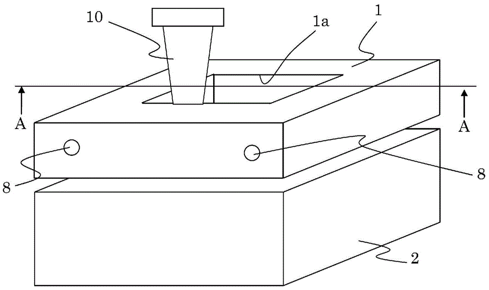
[0073] figure 1 It is a perspective view showing an embodiment of the laser bonding apparatus of a resin case and a metal material according to the present invention. The structure of this embodiment is as follows: As a pressurized fixed mold, a bonded body (resin housing and metal material) is sandwiched between a frame-shaped movable mold, that is, an upper mold 1, and a fixed mold, that is, a lower mold 2, and pressurization, heating.

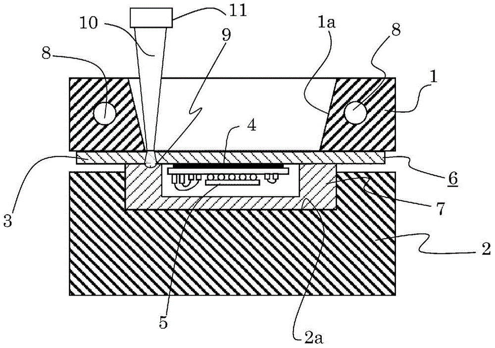
[0074] figure 2 yes means figure 1 A-A sectional view of the detailed composition of . Here, as an example, the case where the sensor member 6 is joined is demonstrated using a schematic diagram. figure 2 The upper mold 1 and the lower mold 2 hold the sensor component 6 mounted with the electronic component 5 fixed on the metal material 3 with an adhesive 4 or the like, and the resin housing 7 . In order to make the laser focusing unit part 11 close to the metal material 3, a hole part 1a is formed in the upper mold 1 in a frame shape...

Embodiment 2

[0082] Figure 4 It is a perspective illustration showing another example of the laser bonding apparatus of resin and metal. figure 1 , figure 2 of resin and laser bonding devices, for the described figure 1 The components shown in , which have the configuration and function assigned the same symbols, will not be described again.

[0083] In this embodiment, an example in which the joint shape of the resin housing and the metal material is enlarged will be described. That is, it is constituted as follows: a central portion of a frame-shaped upper die 1 is provided with a pressurizing block 30 for uniformly pressing the metal material 3 and a transparent material 31 for fixing the upper die 1 and the pressurizing block 30 ( For example, glass, etc.). The laser light 10 passes through the transparent material 31 .

[0084] Figure 5 yes means Figure 4 A-A sectional view of the detailed composition of . It is configured as follows: a transparent material 31 for fixing the...

Embodiment 3

[0087] Figure 6 It is a cross-sectional view showing another example of the resin and metal laser bonding method of the present invention. It is constituted as follows: another material 40 (metal material, ceramics, etc.) having a large light absorption rate for joining is provided on the upper surface portion of the metal material 3 to be joined. From this, it was found that the resin housing 7 and the metal material 3 can be joined uniformly with high strength by generating heat conduction in the joined metal material 3 via the other material 40 . For example, when it is desired to join aluminum and copper, by using a stainless steel material with a large laser absorption rate in the infrared region and a small thermal conductivity, the effect of high-strength and uniform bonding can be exerted with less laser irradiation energy. That is, by using another material 40 with a small thermal conductivity, the energy irradiated to the junction during heating does not diffuse wi...


PUM

PropertyMeasurementUnit
depthaaaaaaaaaa

Abstract

Provided is a laser joining apparatus for joining a metal material and a resin housing made from a thermoplastic resin, wherein the laser joining apparatus enhances the efficiency of heat conduction and reduces the output of the laser beam. A joining apparatus that heat-joins the joint surfaces of a resin housing (7) and a metal material (3) by applying a laser to the surface of the metal material (3) on the opposite side of the joint surface, wherein the resin housing (7) and metal material (3) are positioned and fixed by an upper mold (1) and a lower mold (2) and the joint surfaces of the resin housing (7) and metal material (3) are brought into close contact by pressing the upper mold (1). At this time, the metal material (3) is preheated by a heater (8). A laser beam is applied thereafter from a hole (1a) in the upper mold (1). The efficiency of heating the metal material (3) using the laser can be enhanced, the laser output can be reduced, and the cost of joining can be vastly reduced by heating the resin housing (7) and metal material (3) to a predetermined temperature using the heater (8) and pressurizing the joint surfaces using the upper mold (1) and lower mold (2).

Description

technical field [0001] The present invention relates to an apparatus and method for thermally joining resin and metal by laser. Background technique [0002] Since thermoplastic resin has excellent processability and a large degree of freedom in its shape, it is widely used in general industrial applications such as automobiles, electrical equipment, medical and biological equipment, and has spread to such an extent that it can be said that there is no field where thermoplastic resin is not used. materials around people. With recent CO 2 In the trend of emission control and cost reduction, thermoplastic resins are becoming more functional and replacing metals. Among the replacements for metals, thermosetting resins containing carbon fibers are also becoming popular. However, thermoplastic resins and thermosetting resins tend to be lower in heat resistance temperature and mechanical strength than general metals. In addition, compared with metals, thermoplastic resins and t...

Claims


Application Information

Patent Timeline
Patent Type & Authority Applications(China)
IPC IPC(8): B29C65/16
CPCB23K37/0408B23K26/0006B23K26/0078B23K26/0876B23K26/246B23K26/3213B23K26/3246B23K2201/42B23K2203/08B23K2203/10B23K2203/18B29C65/1612B29C65/1616B29C65/1654B29C65/18B29C65/44B29C65/8215B29C66/0242B29C66/112B29C66/1122B29C66/114B29C66/30321B29C66/43B29C66/53461B29C66/7392B29C66/7394B29C66/742B29C66/7422B29C66/74281B29C66/74283B29C66/74285B29C66/7461B29C66/81267B29C66/81431B29C66/8322B29C66/836B29C66/919B29C66/9192B29C2791/009B29L2031/3481B23K26/244B23K26/32B23K26/324B23K26/3584B23K2101/42B23K2103/02B23K2103/05B23K2103/08B23K2103/10B23K2103/12B23K2103/14B23K2103/18B23K2103/26B23K2103/42B23K2103/52B29C66/02245B29C66/24245B29C66/652B29C66/71B29C66/73161B29C66/73771B29C66/73775B29K2081/06B29K2081/04B29K2079/085B29K2071/00B29K2069/00B29K2067/006B29K2067/003B29K2059/00B29K2055/02B29K2033/12B29K2027/18B29K2027/08B29K2027/06B29K2025/08B29K2025/06B29K2023/38B29K2023/12B29K2023/06
Inventor 角田重晴荒井聪
Owner HITACHI LTD
Why Eureka
Try Eureka