Eureka AIR delivers breakthrough ideas for toughest innovation challenges, trusted by R&D personnel around the world.

Technique for creating a machine to route non-packetized digital signals using distributed RAM

a distributed ram and digital signal technology, applied in the field of non-packetized digital signal routing or switching system, can solve the problem of limited frequency demands on the devices driving the receiving and output electronics, and achieve the effect of high speed

Inactive Publication Date: 2007-03-06
KONINKLIJKE PHILIPS ELECTRONICS NV
View PDF24 Cites 0 Cited by
  • Summary
  • Abstract
  • Description
  • Claims
  • Application Information

AI Technical Summary

Benefits of technology

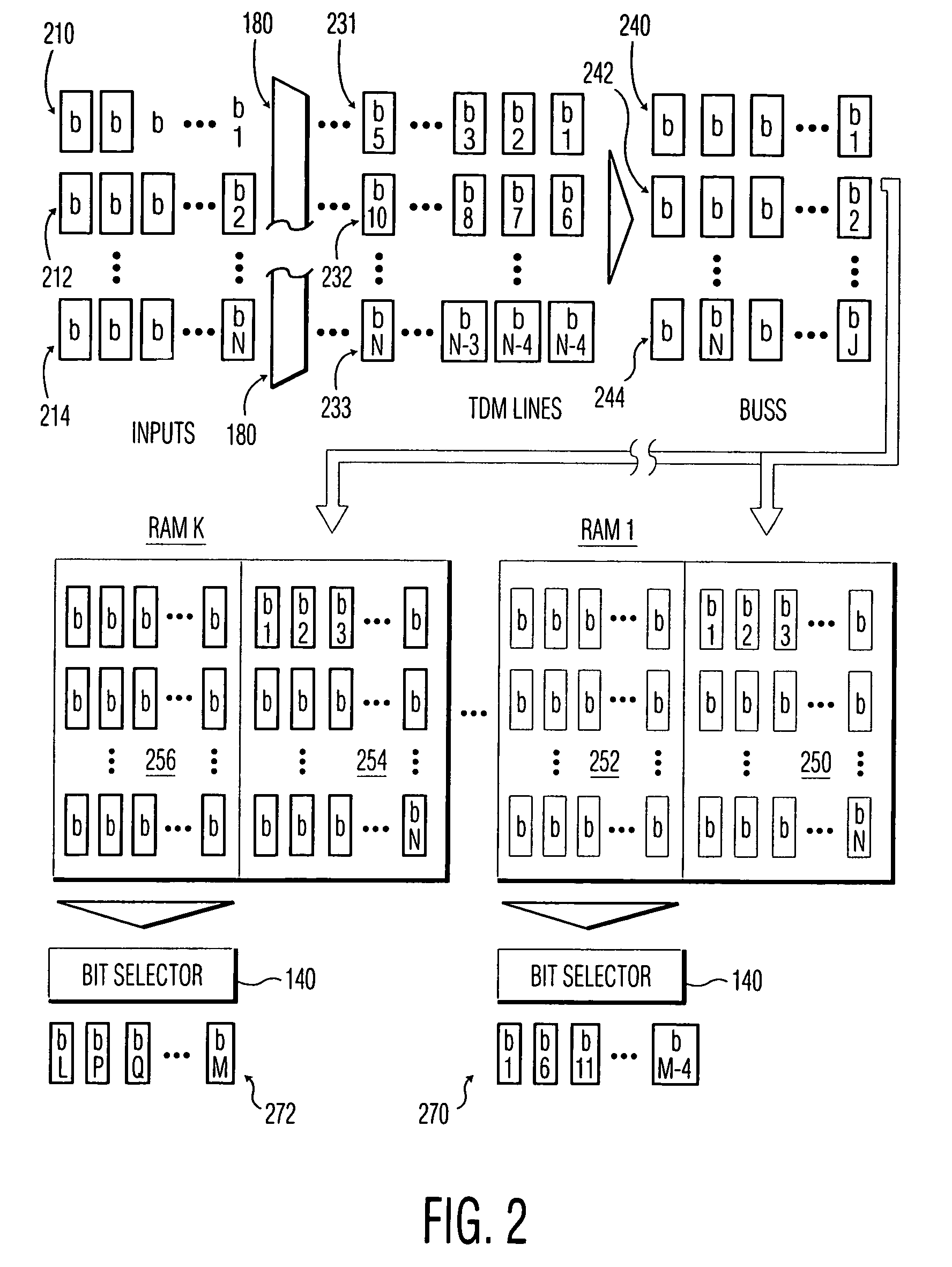
[0006]The technique is possible because of the high speed of large fast data busses and the electronics capable of addressing them. All incoming data on multiple physical channels, each of which may be time multiplexed, is applied to a single large buss. RAM that is capable of storing data on such high speed busses are written to with successive blocks of data from the buss. In a sense, the many-to-many physical switch interconnects characteristic of the spatial multiplexed aspect of the switch are replaced by a single interconnect—the high speed buss—like the hub of a wheel. Thus, interconnect complexity does not scale at the high rate characteristic of spatially multiplexed switches. Rather, the physical switch complexity scales linearly with the number of endpoints. In addition, the frequency demands on the devices driving the receiving and output electronics can be limited as the number of endpoints grows.

Problems solved by technology

In addition, the frequency demands on the devices driving the receiving and output electronics can be limited as the number of endpoints grows.

Method used


Image

  • Technique for creating a machine to route non-packetized digital signals using distributed RAM
  • Technique for creating a machine to route non-packetized digital signals using distributed RAM
  • Technique for creating a machine to route non-packetized digital signals using distributed RAM

Examples


Embodiment Construction

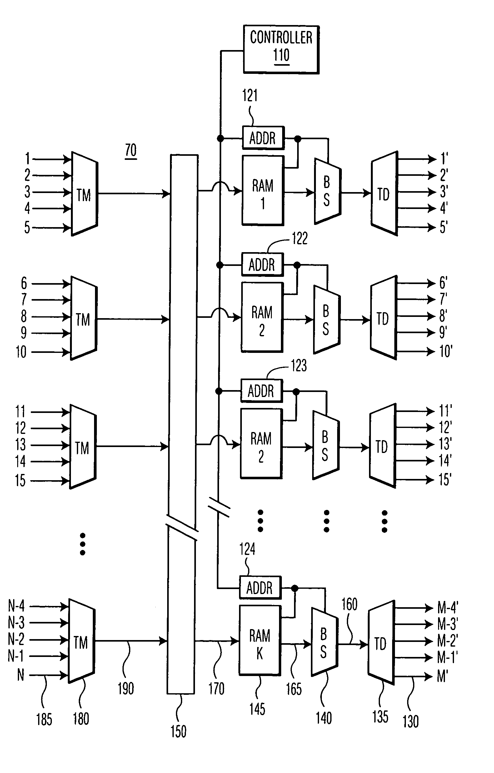
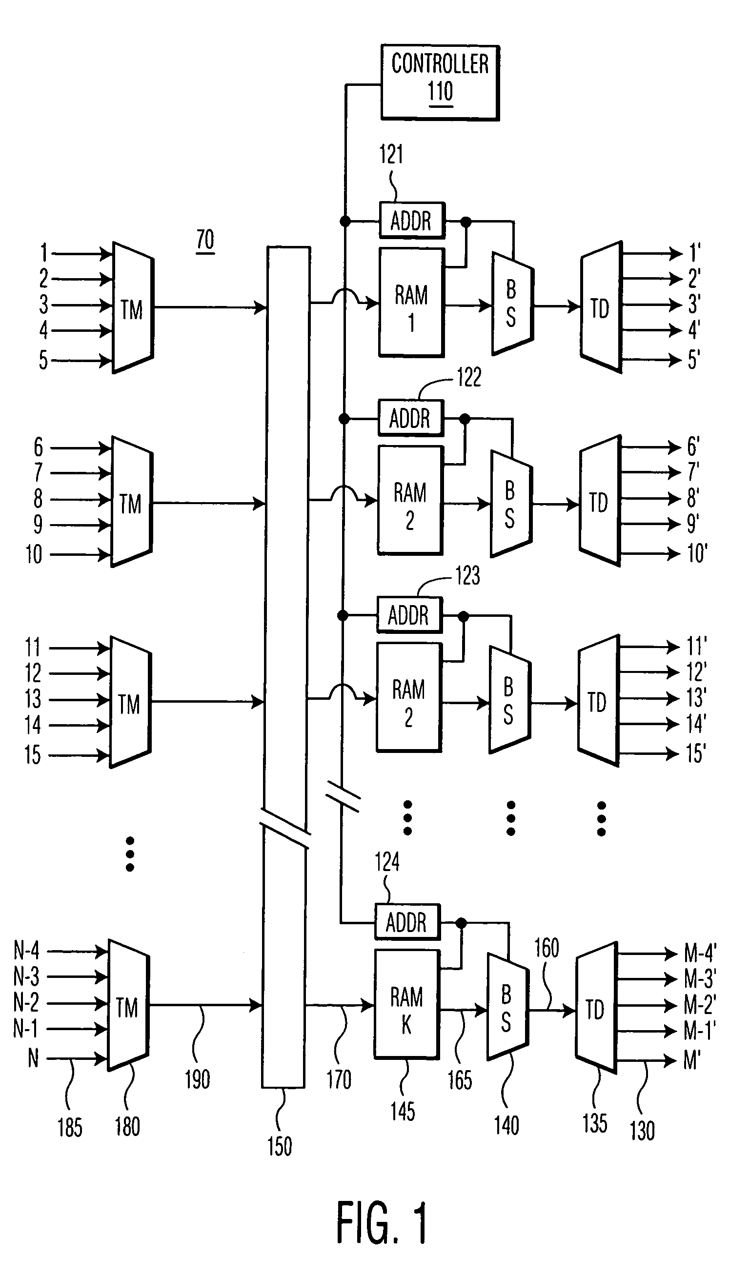
[0010]Referring to FIG. 1, signals on separate physical channels 185 arrive at respective time multiplexers 180 of a switch 70 (generically, a signal transducer). The multiplexers 180 multiplex the several separate signals arriving on the respective physical channels 185 and output them on respective channels 190. The channels 190 may be applied to a buss 150 and read simultaneously into each of several random access memories (RAMs) 145. The RAMs 145 are simultaneously imaged with data from the buss 150 in blocks of arbitrary size, in an embodiment, each block containing one bit from each physical channel 185. As a block is being written, another block is being read. The blocks may correspond to arbitrary areas of memory and reused so that the writing and reading operations over a given block alternate.

[0011]Each RAM 145 is read out by a respective addressing controller 121–124 controlled by a controller 110. As would be understood by a person of ordinary skill, the addressing contr...


PUM


Abstract

A signal router routes N inputs to M outputs. All inputs signals are ultimately applied to a data buss by spreading across multiple buss lines and time multiplexing. The data are read from the buss and written in identical images to K random access memories. The memories are addressed and read according to a different schedule for each of K output signals that are ultimately demultiplexed to M outputs. As each RAM image is read, another RAM image is written and vice versa. Since each RAM image contains the same data, the generation of signals from each RAM to supply each of the respective K output signals can be done at a rate that is substantially more independent of the input, buss, or RAM write operations than prior art techniques permit.

Description

FIELD OF THE INVENTION [0001]The invention relates to non-packet signal routing or switching systems and more particularly to such systems that apply signals from a selected one of N sources to a selected one of M sinks.BACKGROUND [0002]In broadcast systems, video and audio data are transmitted between N originating sources to M destination sinks. Such systems cannot easily rely on packet networking technology because of the need for synchronization of the data. The sources may be recording from CD players, live feeds, digital video files, etc. The control of a broadcast facility may involve rapid switching between many such sources and sinks. Presently, there are three types of routers that are used for such systems: space multiplexing, time multiplexing, and a combination of the two. In space multiplexing, a different physical channel is formed between the source and sink as in a classic telephone switching system. In time multiplexing, all sources and all sinks are connected to t...

Claims


Application Information

Patent Timeline
IPC IPC(8): H04L12/50H04N5/00H04N7/08H04N7/081H04Q11/04
CPCH04Q11/04H04Q2213/13103H04Q2213/13292H04Q2213/13299H04Q2213/1334H04Q2213/13341H04L12/28
Inventor CHRISTENSEN, LEO CARL
Owner KONINKLIJKE PHILIPS ELECTRONICS NV
Why Eureka
Eureka Blog
Learn More