
Method of load and failure prediction of downhole liners and wellbores

a technology of failure prediction and downhole liners, which is applied in the direction of survey, instruments, borehole/well accessories, etc., can solve the problems of reducing the formation fluid pressure, affecting the formation strength and strength distribution analysis of most oil companies, and sand production from the formation and plugging of the borehole, so as to reduce the formation fluid pressure

Inactive Publication Date: 2007-03-06
CONOCOPHILLIPS CO
View PDF15 Cites 35 Cited by
  • Summary
  • Abstract
  • Description
  • Claims
  • Application Information

AI Technical Summary

Benefits of technology

[0014]Stresses applied in the model may include stresses produced by reservoir depletion and an associated decrease in formation fluid pressure. This makes it possible to predict lining of casing failure in a producing reservoir.

Problems solved by technology

Regardless of the device used and the method of deployment, the line and gravel pack must be designed to withstand the stresses in the subsurface formation: failure of the screen or a breakdown of the gravel pack can lead to sand production from the formation and plugging of the borehole.
Of these factors, permeability, permeability distribution, grain size, and grain distribution can be measured with reasonable accuracy; however, most oil companies still have difficulty conducting formation strength and strength-distribution analyses.
The two primary reasons for poor analysis are that mechanical logs available from service companies are not reliable or must be calibrated with other methods and that reasonably reliable numerical models for strength analysis are owned exclusively by several companies.
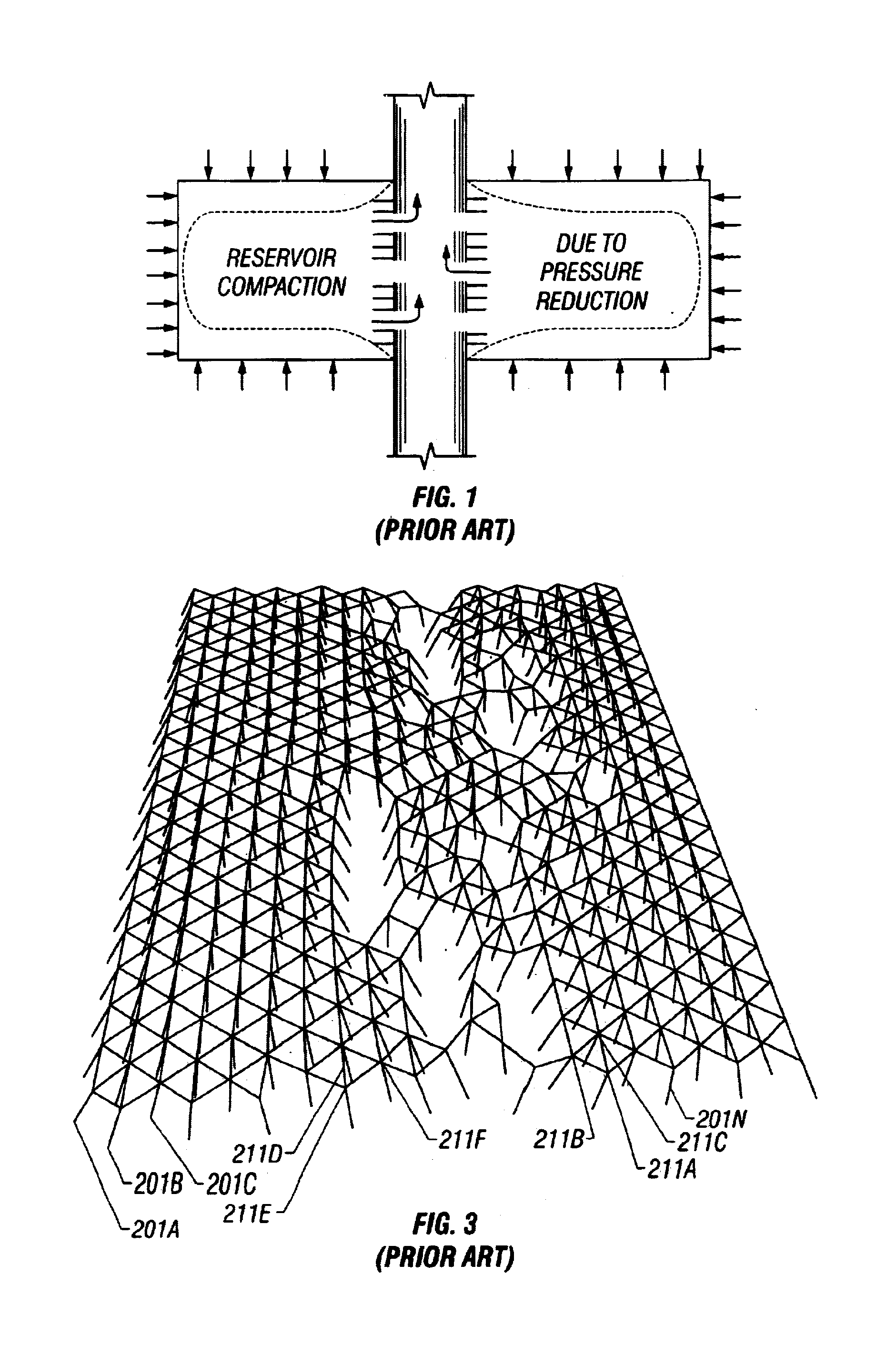
The reduction in pore pressure causes compaction of the formation containing the reservoir fluid, which imposes radial and axial loads on the well.
Wellbore loads resulting from reservoir compaction are seldom considered in the design of casings, liners, and gravel-pack screens, yet they can be significant.
Determining reservoir compaction loads on wellbore tubulars is not a simple task.
Field measurement of reservoir compaction loads is difficult because of the time required for these loads to develop and the difficulty in measuring them.
Simple analytic techniques for calculating reservoir compaction do not account for all the important variables affecting well loads.
As discussed by Hamid et al., liner collapse occurs from application of differential pressures (across the screens) that exceed the collapse strength of the screen jacket.
In general, screen jacket collapse may lead to subsequent long term erosive failure.
In practice, failure usually occurs at the weakest point resulting in asymmetric loading creating localized deformation that can cause early failure of the liner.
Accounting for statistical distribution of properties and the development of local failure areas are impractical to consider using the commonly used finite element analysis techniques.

Method used


Image

  • Method of load and failure prediction of downhole liners and wellbores
  • Method of load and failure prediction of downhole liners and wellbores
  • Method of load and failure prediction of downhole liners and wellbores

Examples


Embodiment Construction

[0025]The present invention uses a Dynamic Range Relaxation Algorithm (DRRA) for the modeling of borehole failure. U.S. patent application Ser. Nos. 09 / 542,307 (the '307 application) filed on Apr. 4, 2000, now U.S. Pat. 6,370,491, and application Ser. No. 09 / 949,966 (the '966 application) filed on Sep. 10, 2001, now U.S. Pat.No. 7,043,410, disclose a method of using a DRRA for the modeling of deformation and fracturing of earth formations on a geologic scale. The present invention uses many of the concepts from the '307 and the '966 application.

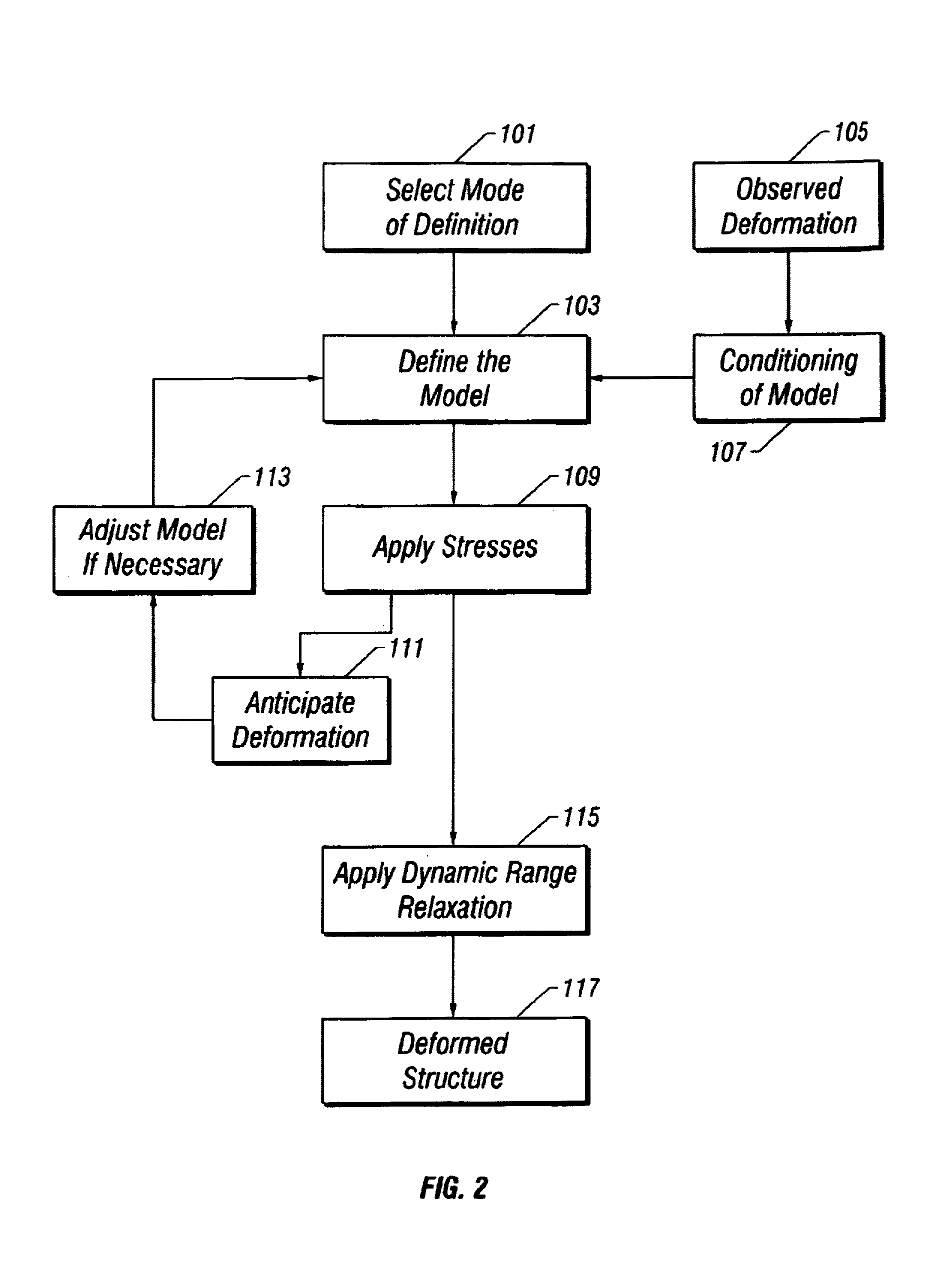
[0026]Turning now to FIG. 2, a flow chart of the major steps of using a DRRA are shown. The first step in the invention isto select a mode of definition of the subsurface 101. This step defines the boundaries of the model and the nodal configuration therein. The mode of definition may be aerial, cross-sectional or 3-D. Within the model, a plurality of interconnected nodes that characterize the geometry of the model are defined. In a preferred...


PUM


Abstract

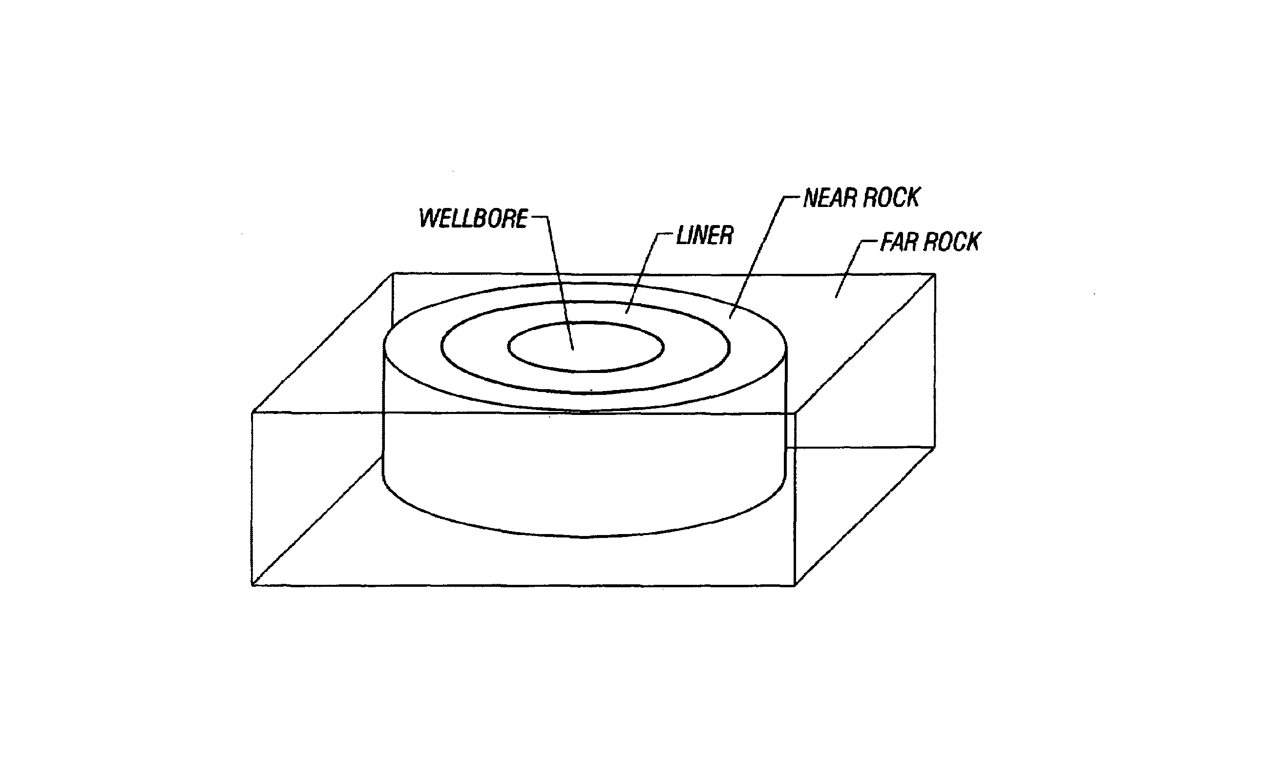
A dynamic range relaxation algorithm is applied to simulate borehole failure under a variety of stress conditions. The borehole and its neighborhood are modeled by a number of regions by a plurality of interconnected nodes. The bonds between the nodes may be modeled as springs, rods, or beams. The strength of the bonds has a statistical variation to accurately simulate real world situations. The model may include, in addition to the borehole and the far earth formations, a liner, a casing, and / or a gravel pack. Simulation is carried out for different strength of the bonds.

Description

REFERENCES TO RELATED APPLICATIONS[0001]This application is a continuation-in-part of U.S. patent application Ser. No. 09 / 949,966 filed on Sep. 10, 2001 that is a continuation-in-part of U.S. patent application Ser. No. 09 / 542,307 Apr. 4, 2000, now U.S. Pat. No. 6,370,491, both of which are incorporated herein by reference.BACKGROUND OF THE INVENTION[0002]1. Field of the Invention[0003]The invention relates to a method for modeling stresses in the vicinity of a borehole and predicting the failure of liners or screens.[0004]2. Background of the Invention[0005]Sand control screens are utilized for various purposes in subterranean wells. The name derives from their early use in preventing the production of sand along with fluids from formations. A sand control screen is typically suspended from production tubing extending to the earth's surface and positioned in a wellbore opposite a productive formation. The wellbore in an annular area between the screen and the casing may be filled w...

Claims


Application Information

Patent Timeline
IPC IPC(8): G06G7/48E21B41/00E21B47/00E21B49/00
CPCE21B49/006E21B47/0006E21B47/007
Inventor HARDY, HUMPHREY H.SALAMA, MAMDOUH M.
Owner CONOCOPHILLIPS CO
Learn More