Al technical title is built by PatSnap Al team. It summarizes the technical point description of the patent document.
a technology for connecting and disconnecting apparatuses, which is applied in the direction of wrenches, drilling casings, drilling pipes, etc., can solve the problems of tubular distortion or damage, and the distortion of tubulars by wrenches and tongs. to achieve the effect of reducing the distortion of tubulars
Active Publication Date: 2007-03-13
VARCO I P INC
View PDF84 Cites 79 Cited by
Summary
Abstract
Description
Claims
Application Information
AI Technical Summary
This helps you quickly interpret patents by identifying the three key elements:
Problems solved by technology
Method used
Benefits of technology
[0017]In certain aspects, in such a system both the upper and the lower jaw assemblies of the torque wrench have three movable die carriers which are equally spaced around a tubular to grip the tubular and to reduce distortion of the tubular.
[0018]In one particular aspect either the upper or the lower jaw assembly is securable to a frame that houses the jaw assemblies so that either jaw assembly can be used to rotate a tubular. In one aspect, the three die carriers are moved simultaneously and assist in centering a tubular within the system.
[0019]In certain embodiments torque cylinders used to rotate the die carriers are interconnected via a rocker arm apparatus that allows forces of one die carrier (of an upper or lower jaw assembly) to be reacted through the rocker arm apparatus to another die carrier or carriers of a different level jaw assembly. Such a rocker arm assembly can also facilitate achieving a discrete actual centering of a tubular within the jaws.
Problems solved by technology
Several prior art iron roughnecks and tongs can distort or damage thin-walled tubulars due to the fact that they employ two opposed jaws to clamp a tubular.
With other prior art systems, a spinner may spin a tubular's pin end into a box, but, due to a relatively long tapered pin desired shouldering of the connection may not be achieved and re-clamping of the tubulars with the torque wrench and again rotating one of the tubulars may be required.
Several prior art tongs employ two opposed grippers which apply forces to a tubular in such a manner that the tubular can be distorted or damaged.
Method used
Image
Click on the blue label to locate the original text in one second.
Reading with bidirectional positioning of images and text.
Examples
Embodiment Construction
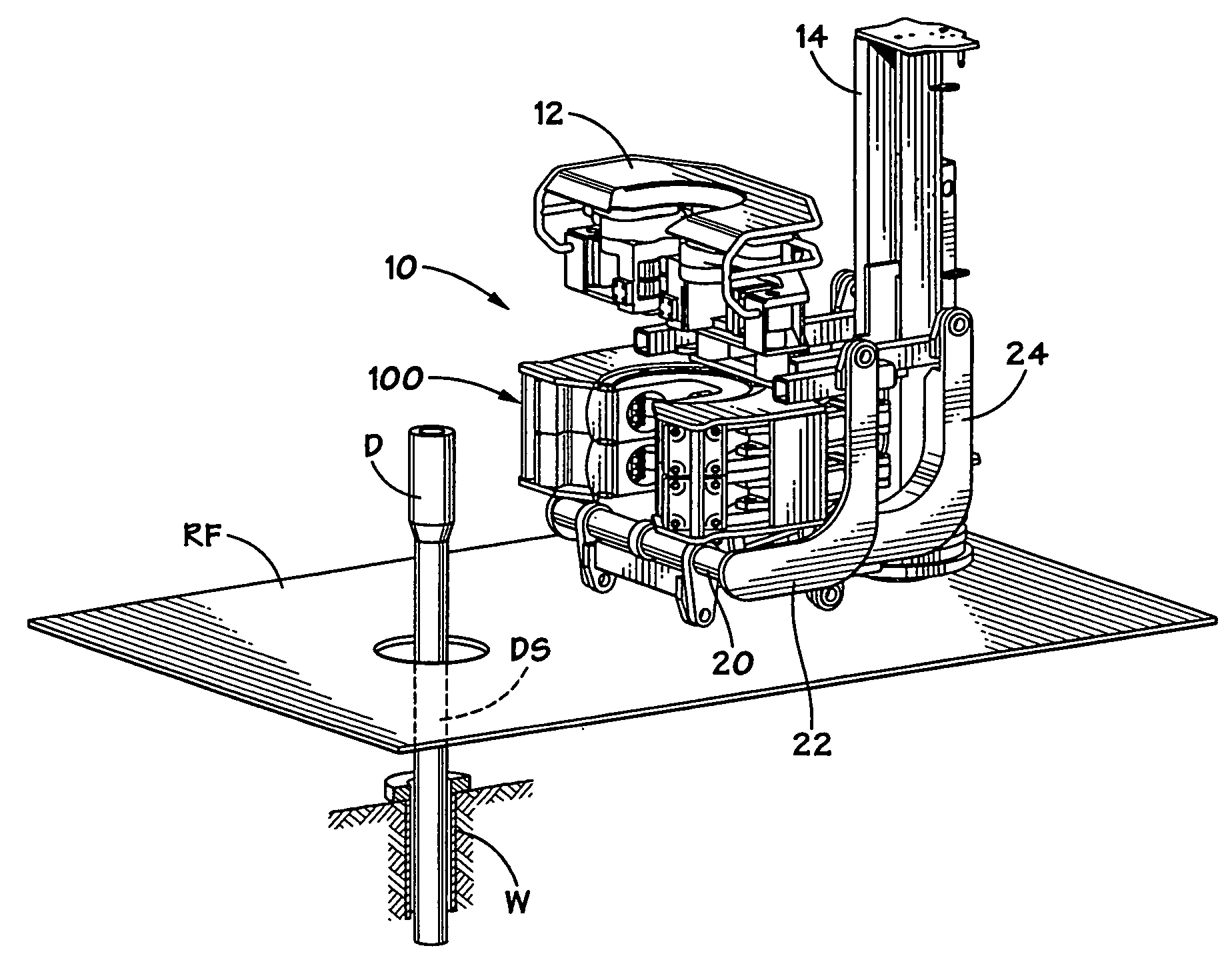
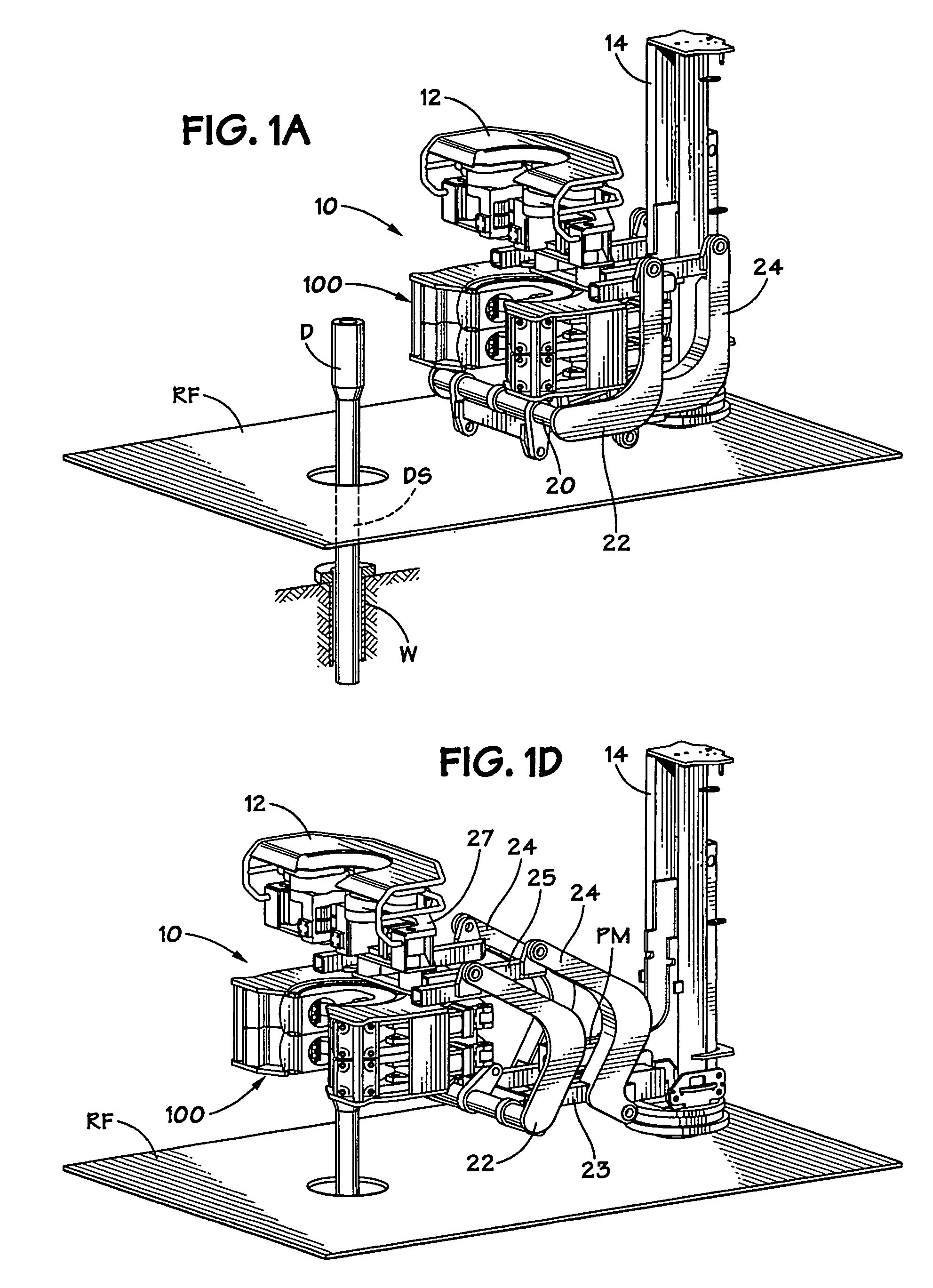
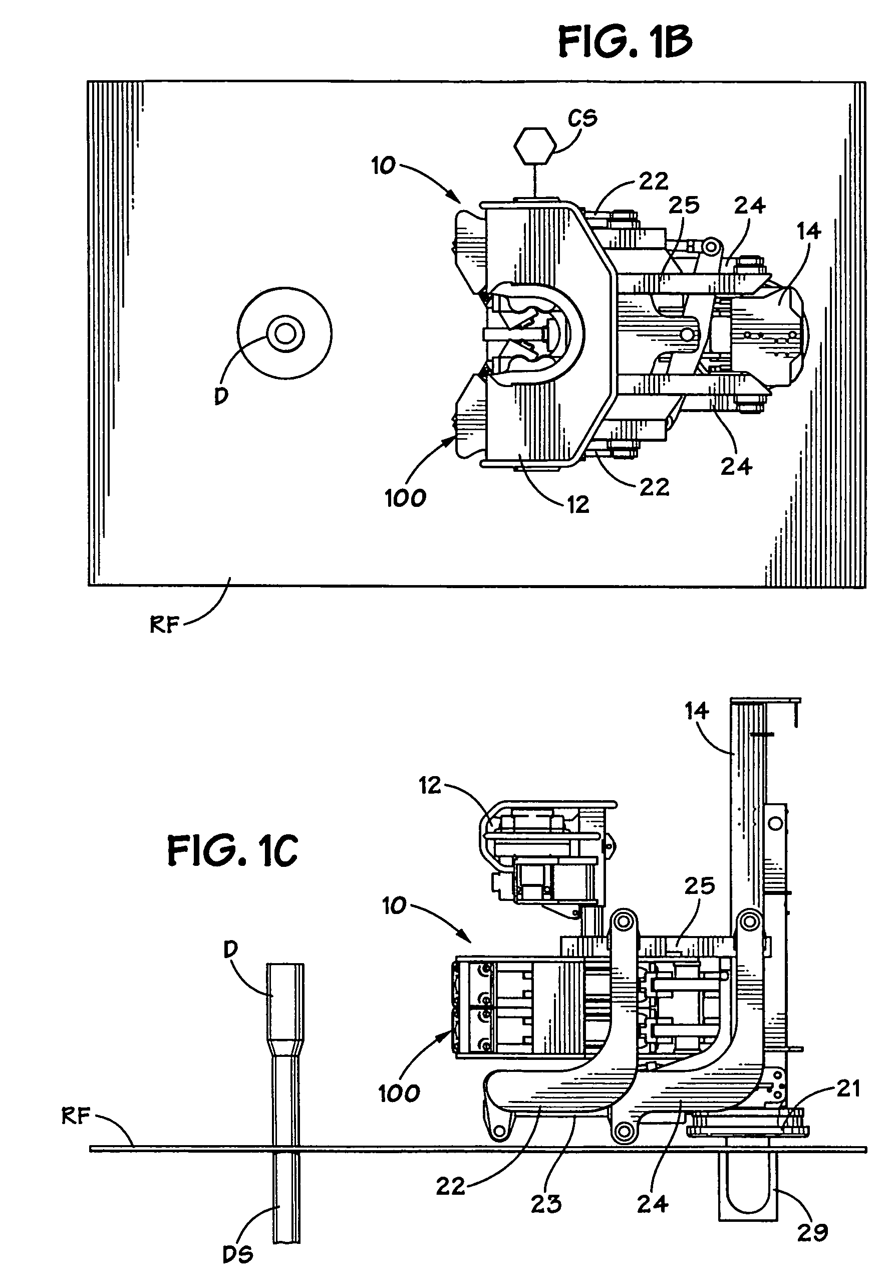
[0059]FIGS. 1A–1D show a system 10 according to the present invention which has a carriage 20 which is movably connected for up / down vertical movement to a column 14 and which can also translate horizontally on a rig floor RF for movement toward and away from a drill pipe D of a drill string DS in a well W. Support arms 22, 24 (two each) are pivotably connected at one end to a base 23 of the carriage 20 and at their other ends to a support 25. Optionally, only one support arm is used or two arms in parallel are used. A connector 21 is removably emplaceable in a socket 29 to mount the system on the rig. In one particular aspect the dual arms move the spinner / wrench combination outwardly 24″ from the column 14 which results in a 6.5″ rise vertically.
[0060]A torque wrench 100 according to the present invention and a spinner 12 are connected to a spin wrench carriage 27 on the support 25 and, are movable by a power mechanism PM toward and away from the column 14 by moving the support ar...
PUM
Abstract
An apparatus for rotating a tubular, the apparatus, in at least certain aspects including a frame, a rocker assembly connected to the frame, the rocker assembly including a top rocker arm pivotably mounted to the frame, and a bottom rocker arm pivotably mounted to the frame, top torque apparatus connected to the frame, upper gripper apparatus connected to the frame for gripping a primary tubular (e.g., but not limited to a first pipe), lower gripper apparatus connected to the frame for gripping a secondary member (e.g., but not limited to a second pipe threadedly connected to or to be threadedly connected to the first pipe; or part of a bit to be connected to or unconnected from a tubular), the upper gripper apparatus and lower gripper apparatus operable so that the lower gripper apparatus grips and holds the secondary member while the upper gripper apparatus grips and holds the primary tubular as the top torque apparatus is rotatable to rotate the primary tubular with respect to the secondary member, and torque generated by the top torque apparatus reacted through the upper gripper apparatus, through the top rocker arm, through the bottom rocker arm, and to the lower gripper apparatus; and methods for using such an apparatus.
Description
RELATED APPLICATION[0001]This is a division of U.S. application Ser. No. 11 / 317,627 filed on Dec. 23, 2005 now U.S. Pat. No. 7,062,991 which is incorporated herein in its entirety for all purposes and from which the present invention claims priority under the Patent Laws.BACKGROUND OF THE INVENTION[0002]1. Field of the Invention[0003]The present invention is directed to apparatuses for connecting and disconnecting tubular members (e.g. casing, tubing, pipe, or drill pipe) and, in certain particular aspects to iron roughnecks, tongs, and methods of their use.[0004]2. Description of Related Art[0005]“Iron roughnecks,” combine a torque wrench and a spinning wrench to connect and disconnect tubulars, e.g. drilling components, e.g. drill pipe, in running a string of tubulars into or out of a well. Prior art iron roughnecks are shown. e.g., in U.S. Pat. Nos. 4,023,449, 4,348,920, 4,765,401, 6,776,070, all of which are incorporated herein by reference in their entirety.[0006]Various prior ...
Claims
Application Information
Patent Timeline
Application Date:The date an application was filed.
Publication Date:The date a patent or application was officially published.
First Publication Date:The earliest publication date of a patent with the same application number.
Issue Date:Publication date of the patent grant document.
PCT Entry Date:The Entry date of PCT National Phase.
Estimated Expiry Date:The statutory expiry date of a patent right according to the Patent Law, and it is the longest term of protection that the patent right can achieve without the termination of the patent right due to other reasons(Term extension factor has been taken into account ).
Invalid Date:Actual expiry date is based on effective date or publication date of legal transaction data of invalid patent.