Systems and methods for quasi-simultaneous multi-planar x-ray imaging

a multi-planar x-ray and imaging system technology, applied in tomography, instruments, applications, etc., can solve the problems of system not being able to move around the hospital as needed, system mounted permanently to the floor and ceiling, imaging system operating independently of one another

Inactive Publication Date: 2007-03-13
MEDTRONIC NAVIGATION INC
View PDF81 Cites 281 Cited by
  • Summary
  • Abstract
  • Description
  • Claims
  • Application Information

AI Technical Summary

Benefits of technology

[0012]An imaging apparatus comprises a gantry having a central opening for positioning around an object to be imaged, a source of radiation that is rotatable around the interior of the gantry and which is adapted to project radiation onto said object from a plurality of different projection angles; and a detector system adapted to detect the radiation at each projection angle to acquire object images from multiple projection planes in a quasi-simultaneous manner. As used herein, the term “quasi-simultaneous” means that there is no appreciable delay between the acquisition of the object images, beyond the time it takes for the source to rotate between different projection angles. In a preferred embodiment, the gantry is a substantially “O-shaped” ring, and the source is rotatable 360 degrees around the interior of the ring. The source can be an x-ray source, and the imaging apparatus can be used for medical x-ray imaging.

Problems solved by technology

One disadvantage of this system is that it is permanently mounted to the floor and ceiling.
Thus, the system cannot be moved about a hospital as needed.
Another disadvantage of this system is that, although the C-arms are coordinated, the imaging systems operate independently of one another.
One disadvantage of this system is that the two imaging systems may not be moved independently of one another.
Thus, the positioning of the second imaging system is limited by the position of the first.
Another disadvantage is that the dual x-ray system is permanently mounted to the floor.
Thus, it cannot be moved about a hospital.
A further disadvantage is that the two images must share a common iso-center because they are nested.
One disadvantage with this system is that the bi-planar images are always disposed at a fixed, perpendicular angle with respect to each other.
Like the ring configuration above, one disadvantage of this system is that the bi-planar images are always disposed at a fixed, perpendicular angle with respect to each other.
Dual imaging systems are complicated and difficult to operate because they require simultaneous coordination and operation of two independent and distinct imaging systems.
In addition, if both imaging systems operate at the same time, the two x-ray beams interact to cause a blurred image.
Moreover, the use of two x-ray sources can result in exposure of the subject to excessive radiation, particularly due to scattering effects.
To date, there does not exist an electromagnetic radiation imaging system that employs a single source to provide simultaneous or near-simultaneous acquisition of object images from multiple projection planes.

Method used


Image

  • Systems and methods for quasi-simultaneous multi-planar x-ray imaging
  • Systems and methods for quasi-simultaneous multi-planar x-ray imaging
  • Systems and methods for quasi-simultaneous multi-planar x-ray imaging

Examples


Embodiment Construction

[0030]A description of preferred embodiments of the invention follows.

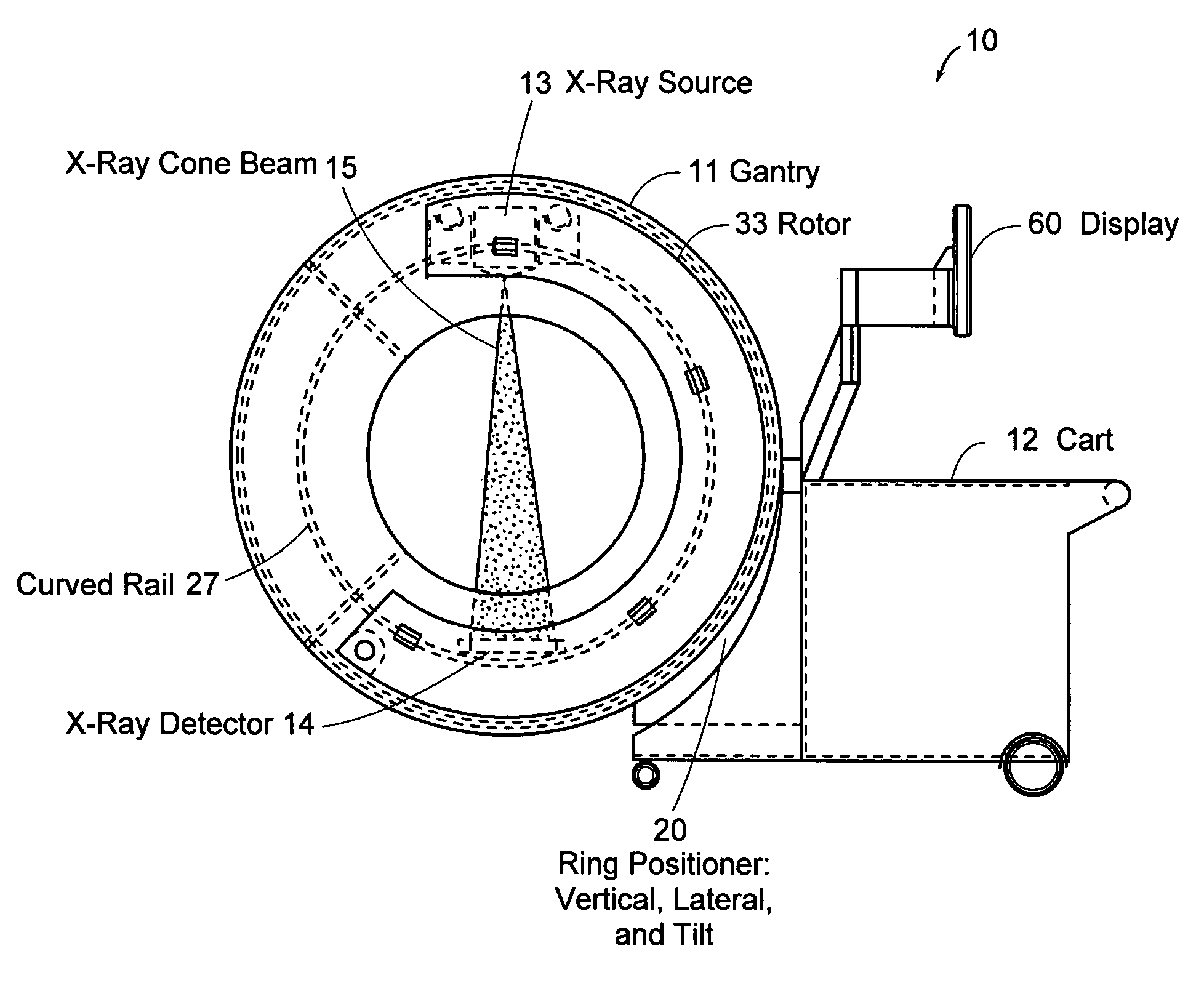
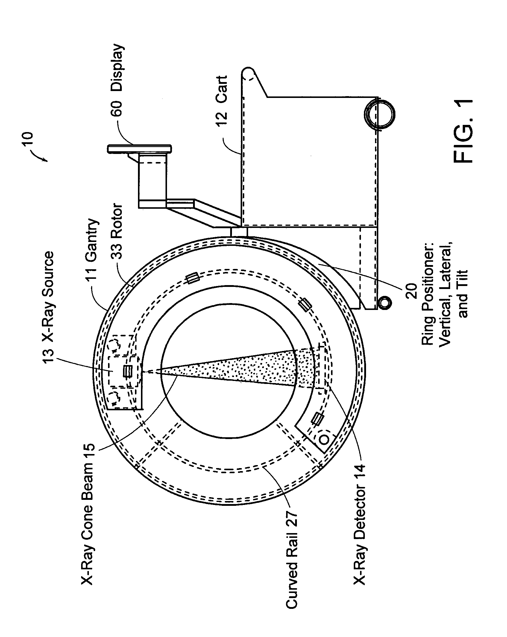
[0031]FIG. 1 is a schematic diagram showing an x-ray scanning system 10 in accordance with one embodiment of the invention. The x-ray scanning system 10 includes a gantry 11 secured to a support structure, which could be a mobile or stationary cart, a patient table, a wall, a floor, or a ceiling. As shown in FIG. 1, the gantry 11 is secured to a mobile cart 12 in a cantilevered fashion via a ring positioning unit 20. In certain embodiments, the ring positioning unit 20 translates and / or tilts the gantry 11 with respect to the support structure to position the gantry 11 in any number of imaging positions and orientations.

[0032]The mobile cart 12 of FIG. 1 can optionally include a power supply, an x-ray power generator, and a computer system for controlling operation of the x-ray scanning device and for performing image processing, storage of x-ray images, or other data processing functions. In a preferred embodimen...


PUM


Abstract

Systems and methods for obtaining two-dimensional images of an object, such as a patient, in multiple projection planes. In one aspect, the invention advantageously permits quasi-simultaneous image acquisition from multiple projection planes using a single radiation source.
An imaging apparatus comprises a gantry having a central opening for positioning an object to be imaged, a source of radiation that is rotatable around the interior of the gantry ring and which is adapted to project radiation onto said object from a plurality of different projection angles; and a detector system adapted to detect the radiation at each projection angle to acquire object images from multiple projection planes in a quasi-simultaneous manner. The gantry can be a substantially “O-shaped” ring, with the source rotatable 360 degrees around the interior of the ring. The source can be an x-ray source, and the imaging apparatus can be used for medical x-ray imaging. The detector array can be a two-dimensional detector, preferably a digital detector.

Description

RELATED APPLICATION[0001]This application claims the benefit of U.S. Provisional Application No. 60 / 363,902, filed Mar. 13, 2002, the entire teachings of which are incorporated herein by reference.BACKGROUND OF THE INVENTION[0002]It is often desirable to take x-rays of a patient from a number of different positions, preferably without the need for frequent manual repositioning of the patient of the x-ray system. Mobile C-arm x-ray diagnostic equipment has been developed for this purpose, and has become well known in the medical art of surgical and other interventional procedures.[0003]A C-arm refers generally to an elongated C-shaped member terminating in opposing distal ends of the “C” shape. An x-ray source and an image receptor are typically mounted at or near the distal ends, respectively, of the C-arm in opposing orientation, with the C-arm supported in a suspended position. The space within the C-shape of the arm provides room for the physician to attend to the patient substan...

Claims


Application Information

Patent Timeline
Patent Type & Authority Patents(United States)
IPC IPC(8): H05G1/04A61B6/00A61B6/02
CPCA61B6/02A61B6/4405A61B6/4441A61B6/035A61B6/56
Inventor GREGERSON, EUGENE A.GRANT, RICHARD K.JOHNSON, NORBERT
Owner MEDTRONIC NAVIGATION INC
Why Eureka
Try Eureka