Balloon alignment and collapsing system

Active Publication Date: 2007-03-13
BOSTON SCI SCIMED INC +1
View PDF21 Cites 41 Cited by
  • Summary
  • Abstract
  • Description
  • Claims
  • Application Information

AI Technical Summary

Benefits of technology

[0011]The axial member within the balloon may incorporate a tube. Desirably, the tube is distensible in the lengthwise direction. A proximal end of the tube is mechanically linked to the proximal end of the balloon. For example, the proximal end of the tube may be mechanically connected to the carrier catheter or to the stop, so that the interior bore of the tube communicates with the lumen of the carrier catheter. The distal end of the tube is mechanically linked to the distal end of the balloon. Thus, when the balloon is deflated, the tube is stretched in the lengthwise direction. When the balloon is inflated, the tube is shortened in the lengt

Problems solved by technology

Simply providing an extension of the carrier catheter projecting distally through the balloon and through the wall of the balloon at the distal end will not allow for such movement unless a sliding se

Method used


Image

  • Balloon alignment and collapsing system
  • Balloon alignment and collapsing system
  • Balloon alignment and collapsing system

Examples


Embodiment Construction

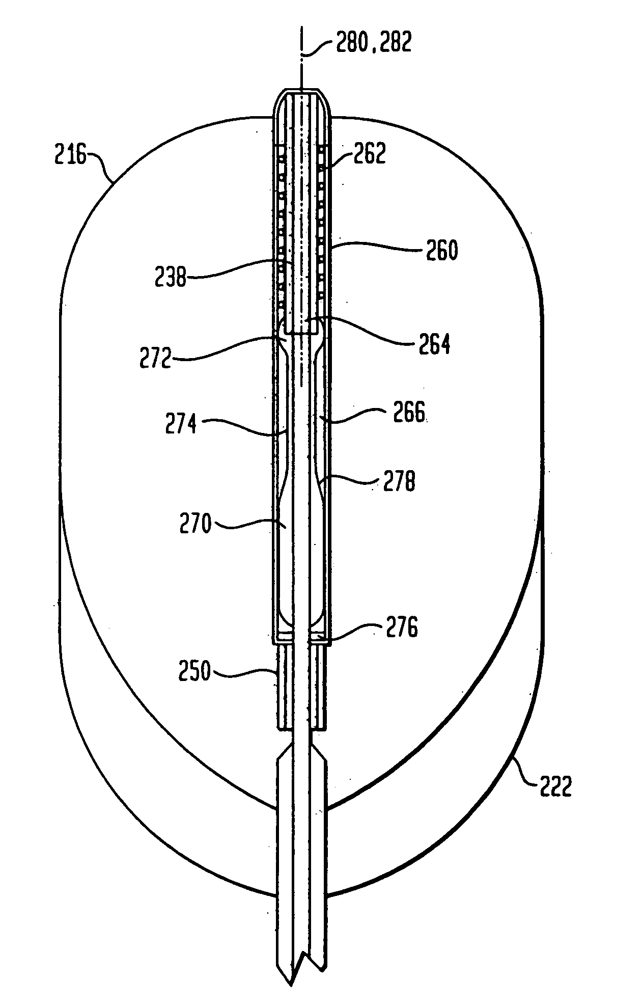
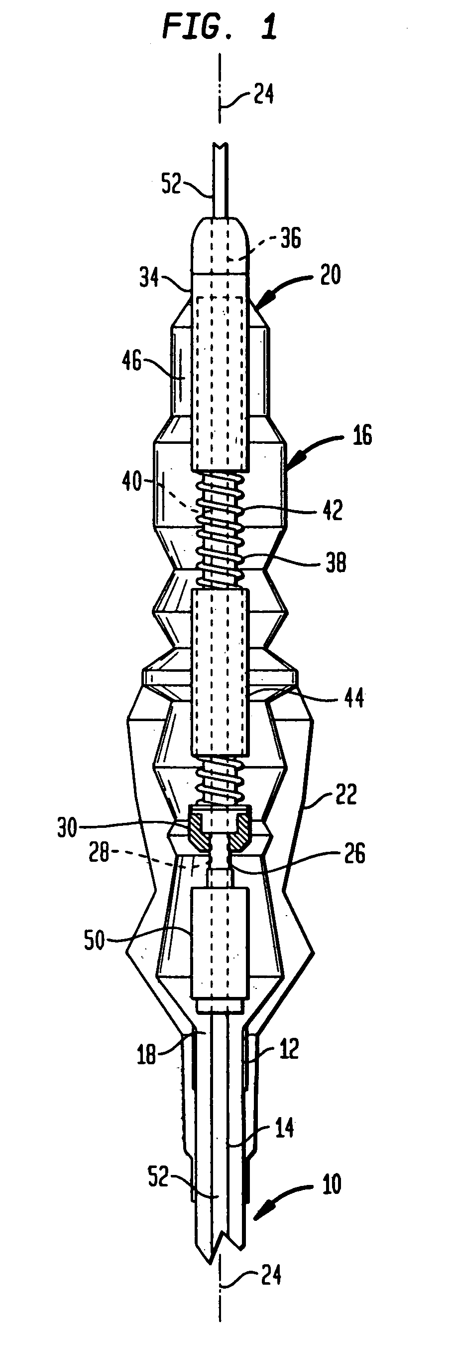
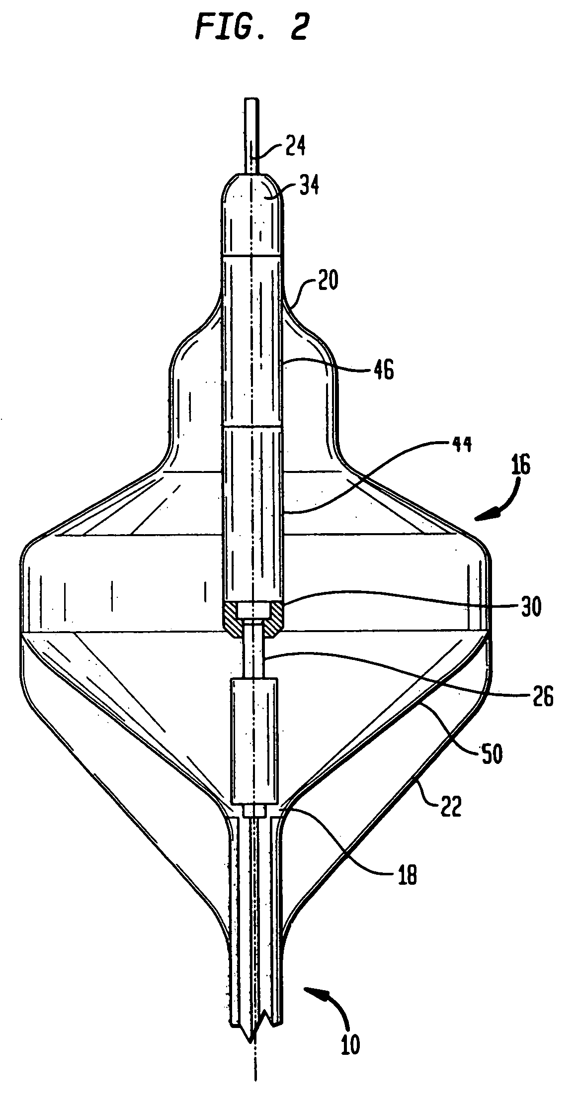
[0020]Apparatus in accordance with one embodiment of the present invention includes a carrier catheter 10 having a distal end 12 and a proximal end (not shown) remote from the distal end. Ordinarily, the proximal end of the carrier catheter is intended to remain outside of the body, or otherwise accessible to the position for manipulation during the procedure, whereas the distal end is intended to be inserted into the body. Carrier catheter 10 has a central lumen 14. A balloon 16 has a proximal end 18 attached to the distal end of the carrier catheter and has a distal end 20 remote from the proximal end. Balloon 16 is shown in an arbitrary, wrinkled shape representing the balloon in a deflated condition. Balloon 16 desirably is formed from a film which is flexible, but which can form a substantially non-compliant balloon structure when inflated. As explained in the '227 application, materials such as those used to form non-compliant balloons in the angioplasty art such as thin films...


PUM


Abstract

A balloon catheter is provided with a sleeve and a flexible material where, upon inflation of the balloon, the sleeve is slid over a ball joint, preventing the flexible material and tube from moving through a range of motion in order to prevent the tube from kinking and misaligning.

Description

CROSS-REFERENCE TO RELATED APPLICATIONS[0001]The present application is a continuation-in-part of U.S. patent application Ser. No. 10 / 244,271, filed Sep. 16, 2002, the disclosure of which is now U.S. Pat. No. 6,808,524 incorporated by reference herein.BACKGROUND OF THE INVENTION[0002]The present invention relates to apparatus incorporating balloons and to techniques employing balloons.[0003]Certain medical and veterinary procedures employ balloons mounted on catheters for various purposes. For example, as described in co-pending, commonly-assigned U.S. patent application Ser. No. 09 / 905,227, published as U.S. Pat. No. 2002 / 0065512-A1, the disclosures of which are hereby incorporated by reference herein, a structure including a balloon is used as a reflector for directing ultrasonic energy from an ultrasonic transducer mounted within the balloon onto a region of tissue to be ablated. As further described in the aforementioned application, the balloon structure also focuses the ultras...

Claims


Application Information

Patent Timeline
IPC IPC(8): A61B18/04A61B18/00A61B17/22A61F2/958A61M25/00A61N7/02
CPCA61N7/02A61M25/10A61B17/2202A61B2017/22054A61M2025/1084A61B2017/22062
Inventor LOPATH, PATRICK DAVIDHARHEN, EDWARD PAULSINELNIKOV, YEGORSAVAGE, JAMES D.MERINO, JAIMEHOTMER, JOHN
Owner BOSTON SCI SCIMED INC
Why Eureka
Try Eureka