
Functional unit enabling controlled flow in a microfluidic device

a microfluidic device and functional unit technology, applied in the field of microfluidic devices, to achieve the effect of lowering the variation in pressure drop between channels

Inactive Publication Date: 2007-03-13
GYROS
View PDF32 Cites 51 Cited by
  • Summary
  • Abstract
  • Description
  • Claims
  • Application Information

AI Technical Summary

Benefits of technology

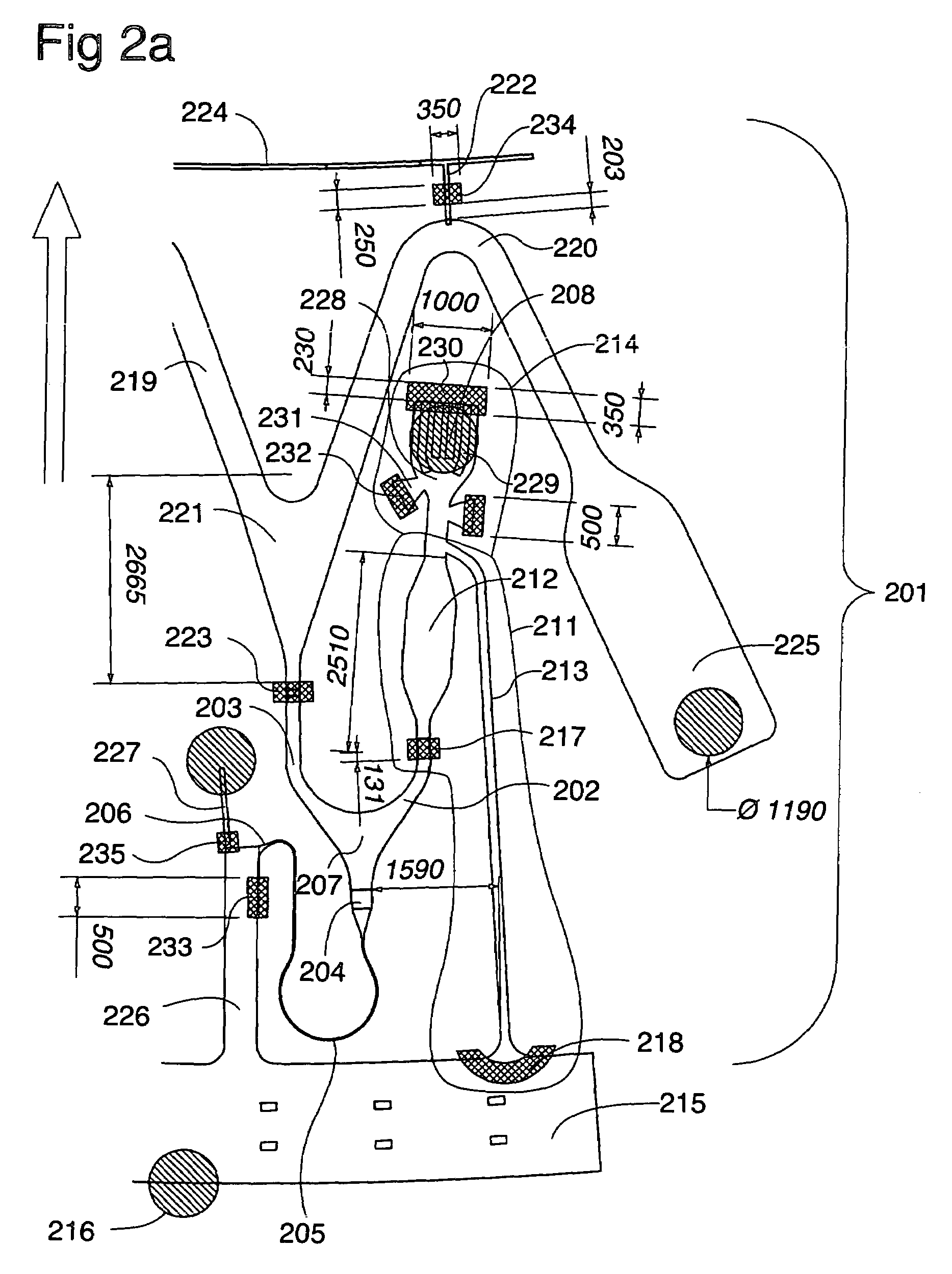
[0016]Yet further, the present invention has also recognized that further benefits may be accomplished if one or more of the following features are also complied with the inventive microfluidic device: (a) porous matrix is placed in the microcavity or immediately downstream this microcavity for creating a significant pressure drop along the matrix; (b) packed bed of monosized particles instead of polysized particles in the microcavity will lower the inter-channel variation in pressure drop along the microcavity; (c) pulse giving increased flow will assist in overcoming inter-channel variations in flow resistance of the individual microchannel structures (this in particular applies when initiating flow and / or when the liquid is to pass through branchings and curvatures); and (d) an anti-wicking means in inner edges downstream and in close proximity to the outlet end of the outlet microconduit, which leads waste liquids from the microcavity.

Problems solved by technology

Typically, microfluidic devices that comprise the above-mentioned structural unit have not comprised any means that will secure parallelity with a low inter-channel variation in flow rate between individual microchannel structures.

Method used


Image

  • Functional unit enabling controlled flow in a microfluidic device
  • Functional unit enabling controlled flow in a microfluidic device
  • Functional unit enabling controlled flow in a microfluidic device

Examples


Embodiment Construction

[0024]A first object of the present invention is to provide a fluidic function that when incorporated into a set of microchannel structures of a microfluidic device will standardize the flow rate through the microcavity, if present, and the outlet microconduit of the microchannel structures of the set, i.e., to control the flow rate such that the inter-channel variation in flow rate is reduced to an acceptable level.

[0025]A second object of the present invention is to provide a robust microfluidic system that can be used for performing a plurality of experiments in parallel for determining reaction variables, e.g., as described in PCT / SE02 / 00537. Typically the determination concerns finding the content of analytes in samples and new and / or optimal binder-ligand combinations, and / or to grade affinity for a range of affinity complexes, ligands and binders, and / or to optimize processes involving formation or dissociation of immobilized affinity complexes under flow conditions.

[0026]A t...


PUM

PropertyMeasurementUnit
volumeaaaaaaaaaa
residence timeaaaaaaaaaa
liquid flow rateaaaaaaaaaa

Abstract

A microfluidic device which comprises two or more microchannel structures (set 1), each of which comprises a structural unit which comprises (i) one or more inlet microconduits, and (ii) an outlet microconduit downstream said one or more inlet microconduits, and (iii) a flow path for a liquid passing through either of said inlet microconduits and said outlet microconduit. The device is characterized in that each outlet microconduit in said two or more microchannel structures is a restriction microconduit. There may also be a microcavity between the inlet microconduit(s) and the restriction microconduit in each microchannel structure. Typically common flow control is used for driving a liquid flow within the device. The innovative design is useful for creating flow with low inter-channel variation with respect to the microchannel structures of the device.

Description

[0001]This application is a continuation in part of International Application No. PCT / SE02 / 00537, which was filed on Mar. 19, 2002; and claims priority to Swedish Application No. 0103117-8, which was filed on Sep. 17, 2001 and U.S. Provisional Application No. 60 / 322,621, which was filed on Sep. 17, 2001.BACKGROUND OF THE INVENTION[0002]A. Field of Invention[0003]The present invention relates to a microfluidic device which comprises two or more microchannel structures (e.g., set 1, set 2, set 3), each of which comprises one or more inlet ports, one or more outlet ports, and a structural unit which is located between an inlet port and an outlet port. The structural unit comprises one or more inlet microconduits, each of which communicates with an inlet port, and an outlet microconduit, which communicates with an outlet port, and an microcavity, which is located between said inlet port and said outlet port. More particularly, the structural unit starts at the inlet ends of the inlet mi...

Claims


Application Information

Patent Timeline
Patent Type & Authority Patents(United States)
IPC IPC(8): B01L3/02B32B5/02B01L11/00B32B27/04B32B27/12B01F5/06B01F13/00B01J19/00B01L3/00B01L99/00G01N33/543G01N35/00
CPCB01F5/0646B01F5/0655B01F13/0059B01J19/0093B01L3/5025B01L3/50273B01L3/502746G01N33/54366B01F5/0647Y10T436/25375B01J2219/00835B01J2219/00891B01L3/502723B01L3/502738B01L2200/06B01L2200/10B01L2200/142B01L2300/069B01L2300/0803B01L2300/0806B01L2300/0861B01L2300/14B01L2300/16B01L2400/0409B01L2400/0633B01L2400/0688G01N35/00069G01N2035/00504Y10T436/111666Y10T436/25Y10T436/11Y10T436/2575B01F25/4331B01F25/433B01F25/4338B01F33/30
Inventor ANDERSSON, PERTHORSEN, GUNNARKYLBERG, GUNNAR
Owner GYROS
Learn More