

Method of modifying crosslinked rubber
- Summary
- Abstract
- Description
- Claims
- Application Information
AI Technical Summary
Benefits of technology
Problems solved by technology
Method used
Image

Examples
example 1
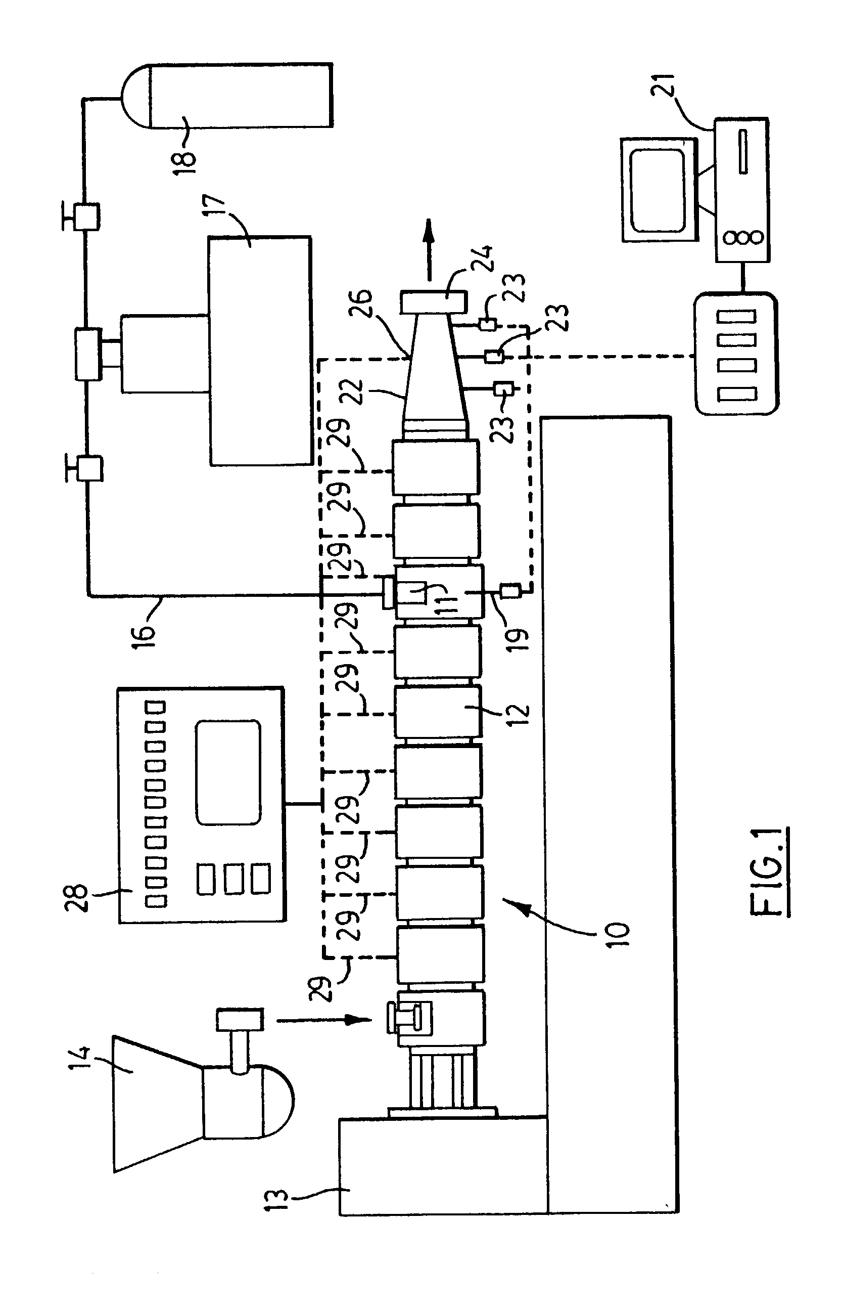
[0025]In the present example, a twin-screw compounding extruder 10 as illustrated in FIG. 1 was used for the production of recycled rubber using a high pressure supercritical carbon dioxide injection system.
[0026]Two types of materials, fine powders (40–60 mesh) (250 microns to 420 micron particle size) and granules (4–8 mesh) (2.38 mm to 4.76 mm particle size), were obtained (ex Huronco, Huron Park, Ontario, Canada). They were processed at various temperatures and feed rates in the extruder 10 equipped with a gas injection port 11. The extruder used is a Leistritz LSM 30.34, intermeshing and co-rotating twin-screw machine having a 34 mm screw diameter operating in a barrel 12 and driven through a gear box 13. Rubber particles were fed by a K-Tron feeder 14 (LWFD 50200), and CO2 was injected into the extruder along a line 16 through the injection port 11 on the barrel 12 using a positive displacement syringe pump 17 connected to a CO2 cylinder 18. The pressure at the barrel injectio...
example 2
[0049]80 mesh SBR rubber was devulcanized at 250° C. using rubber feed rates, as supplied by the feeder 14, of 15 g / min and 30 g / min. The CO2 concentrations were varied. The contents of low m.w. substances, sol, and total soluble (low m.w. plus sol) were obtained for the starting material SBR rubber and for the devulcanized products, and are shown in Table 4 in weight percent based on the total weight of the sample.
[0050]
TABLE 4StartingFeed rate 15 g / minFeed rate 30 g / minmaterialCO2 concentrationCO2 concentrationSBR1%2%3%1%2%3%Low m.w.6989998Sol2171617171418Total8262426262326solubles
[0051]It will be noted that extrusion with supercritical CO2 resulted in an increase of the soluble fraction from 8% in the starting powder to about 26% in the devulcanized material. Also, it can be seen that changes in feed rate and CO2 concentration did not have an effect on the soluble fraction in the rubber. Furthermore, it will be noted that the soluble part consists mainly of sol resulting from dev...
example 3
[0052]Example 2 was repeated at barrel temperatures of 200° C. and 250° C., with screw speeds of 25 and 50 rpm and 2 wt % CO2. The results are shown in Table 5.
[0053]
TABLE 5Temp.200° C.250° C.Screw speed (rpm)25502550Low m.w.8989Sol9111418Total solubles17202227
[0054]The results show that increasing screw speed leads to increased shearing and therefore increased devulcanization.
[0055]In order to study the changes in properties after devulcanization through extrusion, products were revulcanized with curing agents. Two samples were prepared using devulcanized SBR 40 mesh obtained following the procedure as described in the Examples above with 2.1 wt % CO2 and 4.6 wt % CO2 concentration at 250° C., 50 rpm. These samples were compounded according to the following recipe:
[0056]
TABLE 6IngredientParts by weightDevulcanized Rubber100Sulphur POLYBOUND ™ 80%*1.2MBTS 301 POLYBOUND ™ 80%*0.6TMTD 304 POLYBOUND ™ 80%*0.6
[0057]The samples were milled on a Farrel Laboratory mill with size 28 cm leng...
PUM
| Property | Measurement | Unit |
|---|---|---|
| Fraction | aaaaa | aaaaa |
| Fraction | aaaaa | aaaaa |
| Fraction | aaaaa | aaaaa |
Abstract
Description
Claims
Application Information