Two-wire dimmer with power supply and load protection circuit in the event of switch failure

a load protection circuit and power supply technology, applied in the field of two-wire dimmers with power supply and load protection circuits in the event of switch failure, can solve the problems of increasing the temperature of the transformer, fire hazards, and dc components of the voltage across the transformer, and achieve the effect of minimizing the overheating of the inductive load

Active Publication Date: 2007-03-13
LUTRON TECH CO LLC
View PDF21 Cites 136 Cited by
  • Summary
  • Abstract
  • Description
  • Claims
  • Application Information

AI Technical Summary

Benefits of technology

[0011]The present invention provides a dimmer circuit for providing AC power from an AC voltage source to an inductive lighting load disposed in series with the dimmer circuit comprising a bidirectional semiconductor switch having at least one control electrode provided with a control signal for controlling the amount of power provided to the load, the switch in normal operation being able to be controlled to block voltage in first and second opposite polarity half-cycles of the AC voltage source but in a failure mode being able to block voltage in only one half-cycle of the AC voltage source and not being able to block voltage in the second opposite polarity half-cycle; a controller for the switch for determining if said failure mode of the switch occurs; a power supply for supplying power to the controller and provided with power across the dimmer circuit; the controller controlling the switch if such failure mode occurs so as to: drive the switch into substantially full conduction during most of the half-cycle which the switch is able to control; and drive the switch into non-conduction for a brief interval of time during that same half-cycle so as to prevent a DC voltage component supplied to the load from exceeding a predetermined level below which excessive transformer heating does not occur, thereby minimizing overheating of the inductive load and enabling the power supply for the controller to be provided with sufficient voltage from the AC voltage source to enable the controller to continue to operate.
[0012]According to the present invention, where the bidirectional switch comprises two anti-series connected FETs, and one of the switches has failed, the controller of the dimmer circuit drives the non-failing switch into full conduction during most of the half-cycle which the switch is able to control and drives the switch into non-conduction for only a brief period of time during that half-cycle so as to prevent the DC voltage level being supplied to the attached load from exceeding a predetermined level, below which level excessive transformer overheating does not occur, and enables the power supply to be provided with sufficient voltage to enable the controller to continue to operate. In this way, the controller can continue to operate and can provide a fault signal indicating that a fault has occurred in the dimmer, for example, blinking a indicator on a user interface of the dimmer. Further, there is no danger that the magnetic low-voltage lamp load will overheat excessively to a point that it presents a hazard because the DC level is maintained below the predetermined level. Thus, the circuit according to the present invention protects the load from damage as well as protecting the dimmer circuit itself from further damage and enables the controller of the dimmer circuit to continue to operate.
[0013]The present invention also provides a method for operating a dimmer circuit for providing AC power from an AC voltage source to an inductive lighting load disposed in series with the dimmer circuit, wherein the dimmer comprises a bidirectional semiconductor switch having at least one control electrode provided with a control signal for controlling the amount of power provided to the load, the switch in normal operation being able to be controlled to block voltage in first and second opposite polarity half-cycles of the AC voltage source but in a failure mode being able to block voltage in only one half-cycle of the AC voltage source and not being able to block voltage in the second opposite polarity half-cycle; a controller for the switch for determining if said failure mode of the switch occurs which can cause an asymmetry between the half-cycles delivered to the load and thus a DC voltage component to be delivered to the load; a power supply for supplying power to the controller and provided with power across the dimmer circuit; the method comprising driving the switch into substantially full conduction during most of the half-cycle which the switch is able to control; and driving the switch into non-conduction for a brief interval of time during that same half-cycle so as to prevent a DC voltage component supplied to the load from exceeding a predetermined level below which excessive transformer heating does not occur, thereby minimizing overheating of the inductive load and enabling the power supply for the controller to be provided with sufficient voltage from the AC voltage source to enable the controller to continue to operate.
[0014]The present invention further provides a method for operating a dimmer circuit for providing AC power from an AC voltage source to an inductive lighting load disposed in series with the dimmer circuit, wherein the dimmer circuit comprises a bidirectional semiconductor switch having at least one control electrode provided with a control signal for controlling the amount of power provided to the load, the switch in normal operation being able to be controlled to block voltage in first and second opposite polarity half-cycles of the AC voltage source but in a failure mode being able to block voltage in only one half-cycle of the AC voltage source and not being able to block voltage in the second opposite polarity half-cycle; a power supply for supplying power to a control circuit for the dimmer circuit and provided with power across the dimmer circuit; the method comprising determining if said failure mode of the switch occurs which can cause an asymmetry between the half-cycles delivered to the load and thus a DC voltage component to be delivered to the load; driving the switch into substantially full conduction during most of the half-cycle which the switch is able to control; and driving the switch into non-conduction for a brief interval of time during that same half-cycle so as to prevent a DC voltage component supplied to the load from exceeding a predetermined level below which excessive transformer heating does not occur, thereby minimizing overheating of the inductive load and enabling the power supply for the control circuit to be provided with sufficient voltage from the AC voltage source to enable the control circuit to continue to operate.

Problems solved by technology

A problem with low-voltage lighting loads employing a transformer, such as magnetic low-voltage (MLV) lighting, is that the transformers are susceptible to any direct-current (DC) components of the voltage across the transformer.
A DC component in the voltage across the transformer can cause the transformer to generate acoustic noise and to saturate, increasing the temperature of the transformer and possibly creating a fire hazard.
However, this is not a universal requirement for magnetic low-voltage lighting loads, and accordingly, it is important to ensure that such magnetic low-voltage lighting loads, particularly where the loads are not thermally protected, are prevented from overheating.
Thus, the problem of overheating an MLV transformer due to a DC component of the voltage is not created.
The end user of the dimmer will know that there is a problem with the dimmer because the connected lighting load will be on at full brightness and the user will not be able to dim the light.
A problem does arise, however, with dimmers that employ FETs as the controlled switching devices.
The problem of overheating an MLV transformer occurs when only one of the FETs fails.
Due to the asymmetry between the two half-cycles, a DC component will be provided to the load, thus creating an overheating hazard.
If no thermal protection is provided, a potential fire hazard exists.
Should one of the switches fail open, there may be an asymmetry if the open failure leaves the body diode (or external diode) intact because in that case one half-cycle will be absent whereas the other half-cycle will be present, also causing an overheating hazard.

Method used


Image

  • Two-wire dimmer with power supply and load protection circuit in the event of switch failure
  • Two-wire dimmer with power supply and load protection circuit in the event of switch failure
  • Two-wire dimmer with power supply and load protection circuit in the event of switch failure

Examples


Embodiment Construction

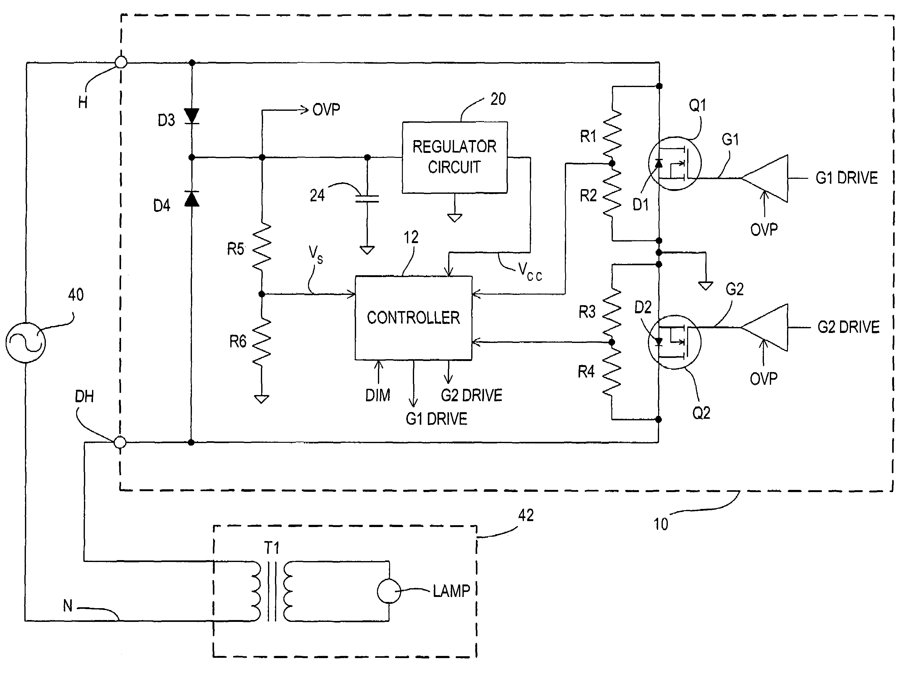
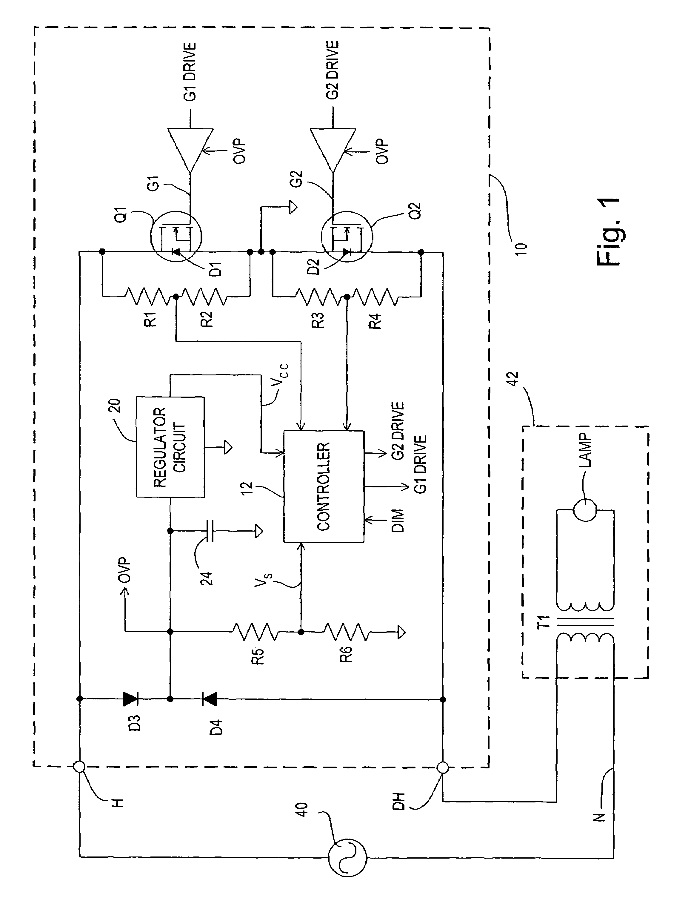
[0031]With reference now to the drawings, FIG. 1 shows a simplified schematic diagram of a dimmer 10 incorporating the principles of the present invention. The dimmer 10 includes first and second semiconductor switches Q1 and Q2 functioning as a bidirectional switch. The switches may be FETs connected in anti-series relationship. The intrinsic body diodes D1 and D2 are shown. Additionally, external diodes can be provided across each of the transistors Q1 and Q2 connected in the same way as the body diode, as shown, to provide a better forward voltage characteristic than the body diode. The two transistors Q1 and Q2 have their gates G1 and G2 controlled by a controller 12, such as a microprocessor, in response to a dimming signal DIM and other inputs (such as on / off) from the user interface (not shown) of the dimmer 10, to provide appropriate dimming and on / off control. Although a microprocessor controller 12 is shown, this circuit need not have a microprocessor and can be an analog ...


PUM


Abstract

A dimmer circuit provides AC power to an inductive lighting load in series with the dimmer circuit. A bidirectional semiconductor switch has a control electrode with a control signal for determining the power provided to the load. The switch in normal operation is controlled to block voltage in first and second half-cycles of the AC voltage. In a failure mode it can block the AC voltage in only one half-cycle. A controller for the switch determines the failure mode of the switch occurs which can cause an asymmetry between the half-cycles and thus a DC voltage component. A power supply supplies power to the controller from across the dimmer circuit. The controller drives the switch into substantially full conduction during most of the half-cycle which the switch is able to control; and drive the switch into non-conduction for a period of time during that same half-cycle so as to reduce the DC voltage component to prevent excessive transformer heating. The power supply is provided with sufficient voltage from the AC voltage to enable the controller to continue to operate.

Description

BACKGROUND OF THE INVENTION[0001]The present invention relates to power supply circuits, and more particularly, to power supply circuits for supplying power to alternating-current (AC) loads, for example lighting dimmer circuits, and wherein the circuit employs a power supply for providing power to a control circuit controlling a switching circuit supplying power to the load and which protects the load in the event of switch failure.[0002]Circuits for providing variable power to AC loads are known, for example, lighting dimmers. Some lighting loads are low-voltage lighting loads, which are supplied with AC power via a step-down transformer, typically an isolation transformer. These step-down transformers step the voltage down to the low-voltage level, for example 12 to 24 volts, necessary to power the lamp or lamps. A problem with low-voltage lighting loads employing a transformer, such as magnetic low-voltage (MLV) lighting, is that the transformers are susceptible to any direct-cu...

Claims


Application Information

Patent Timeline
Patent Type & Authority Patents(United States)
IPC IPC(8): H05B37/02
CPCH05B39/044Y02B20/146Y02B20/00
Inventor KUMAR, RUSSIKESHDEJONGE, STUARTDOLAN, DAVID J.
Owner LUTRON TECH CO LLC
Why Eureka
Try Eureka