Method for production of nitrogen trifluoride from trimethylsilylamines

a technology of trimethylsilylamine and nitrogen trifluoride, which is applied in the direction of nitrogen-metal/silicon/boron binary compounds, inorganic chemistry, chemistry apparatus and processes, etc., can solve the problems of high electricity cost, inability to react with ncl/sub>3/sub>, and typically below 40% of nf/sub>gas, so as to eliminate the cost of cryogenic conditions maintenance and easy aspiration

Inactive Publication Date: 2012-04-24
OMOTOWA BAMIDELE A
View PDF21 Cites 0 Cited by
  • Summary
  • Abstract
  • Description
  • Claims
  • Application Information

AI Technical Summary

Benefits of technology

[0029]The use of a suitable solvent allows the conversion of a large amount of the trimethylsilylamine reagent in Batch or continuous flow processes. The process has to balance the concentration of fluorine feedstock to the overall flow requirement, and to safety. Although, acetonitrile can used as solvent for low temperature fluorination with elemental fluorine, it is hygroscopic, and will be aspirated by high flow processes. An efficient large scale process is best carried out in an aprotic, non-hygroscopic, that may not be easily aspirated from the process. A perfluorocarbon solvent would not react with elemental fluorine, and will allow the operation of these processes at room temperature.
[0030]Trimethylsilyl fluoride is a major byproduct of reaction that will be genera

Problems solved by technology

However, the reaction with NCl3 is not feasible because it is an explosive reagent at temperatures as low −196° C. The production of NF3 involve oxidation of N(3−) to N(3+), and this transformation in commercial processes has required the use of F2 as fluorinating agent.
However, the yield of NF3 gas is typically below 40%, because it is the least favored reaction among three possible mechanisms shown in Table 1.
These strategies have produced high yields for conversion of the ammonium salt to NF3, but have had accompanying high cost of electricity; poor turnover of the F2 fl

Method used


Image

  • Method for production of nitrogen trifluoride from trimethylsilylamines
  • Method for production of nitrogen trifluoride from trimethylsilylamines
  • Method for production of nitrogen trifluoride from trimethylsilylamines

Examples


Embodiment Construction

[0045]While the presently disclosed inventive concept(s) is susceptible of various modifications and alternative constructions, certain illustrated embodiments thereof have been shown in the drawings and will be described below in detail. It should be understood, however, that there is no intention to limit the inventive concept(s) to the specific form disclosed, but, on the contrary, the presently disclosed and claimed inventive concept(s) is to cover all modifications, alternative constructions, and equivalents falling within the spirit and scope of the inventive concept(s) as defined in the claims.

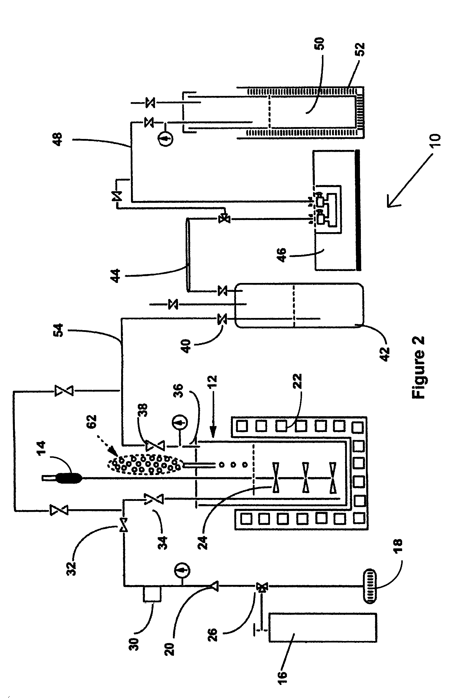
[0046]Shown in FIG. 2 is an example of the production of NF3 from tri(trimethylsilyl)amine and bi(trimethylsilyl)amine in a liquid phase process, designated 10. Shown in FIG. 2 is a laboratory scale version of the method of the invention. Each of the pieces of equipment and quantities of reagents would be scaled up in a production mode, but the laboratory scale version serves as an exam...


PUM


Abstract

Presented is a method for Batch or continuous production of nitrogen trifluoride (NF3) using direct fluorination of organic solution of trimethylsilylamines at low temperatures. Fluorine gas reacts with a solution of tris(trimethylsilyl)amine or bis(trimethylsilyl)amine in a suitable reactor to produce NF3 in a continuous flow process. The crude product can be purified by a channeling the crude process flow through a scrubber to remove reactive byproducts and by cryogenic trapping of other non reactive byproducts in the process flow. Temperatures in the reaction and storage vessels are maintained to control the reaction products based on thermodynamics of the process and products. NF3 is liquefiable at −126 degree Centigrade, and may be collected and used in other processes. The method also produce NF3 as a continuous gas flow process where fluorine is channeled to contact micro droplet suspensions of bis(trimethylsilyl)amines in sulfur hexafluoride.

Description

TECHNICAL FIELD[0001]The present invention generally relates to methods for batch or continuous production of nitrogen trifluoride and more specifically to a method for production of nitrogen trifluoride by direct fluorination of trimethylsilylamines as a low temperature liquid phase process or as a gas phase process.BACKGROUND[0002]Nitrogen trifluoride (NF3) is a colorless, toxic, odorless, nonflammable inorganic gas, with increasing use as an etchant in microelectronics, in the plasma etching of silicon wafers, in the cleaning of the PECVD chambers in the high volume production of liquid crystal displays and silicon-based thin film solar cells. In these applications NF3 is initially broken down in situ, by plasma. The resulting fluorine atoms are the active cleaning agents that attack the polysilicon and silicon oxide. NF3 has been considered as an environmentally preferable substitute for sulfur hexafluoride or perfluorocarbons such as hexafluoroethane.[0003]NF3 can be prepared f...

Claims


Application Information

Patent Timeline
IPC IPC(8): C01B21/083
CPCC01B21/0835
Inventor OMOTOWA, BAMIDELE A.
Owner OMOTOWA BAMIDELE A
Why Eureka
Try Eureka