
Active hybrid transformer circuit having a replica driver

a hybrid transformer and replica technology, applied in the direction of pulse generators, baseband system details, pulse techniques, etc., can solve the problems of low non-linear distortion characteristic, inconvenient high-speed communication, and increase in size, and achieve the effect of simple structur

Active Publication Date: 2007-03-13
RENESAS ELECTRONICS CORP +1
View PDF9 Cites 10 Cited by
  • Summary
  • Abstract
  • Description
  • Claims
  • Application Information

AI Technical Summary

Benefits of technology

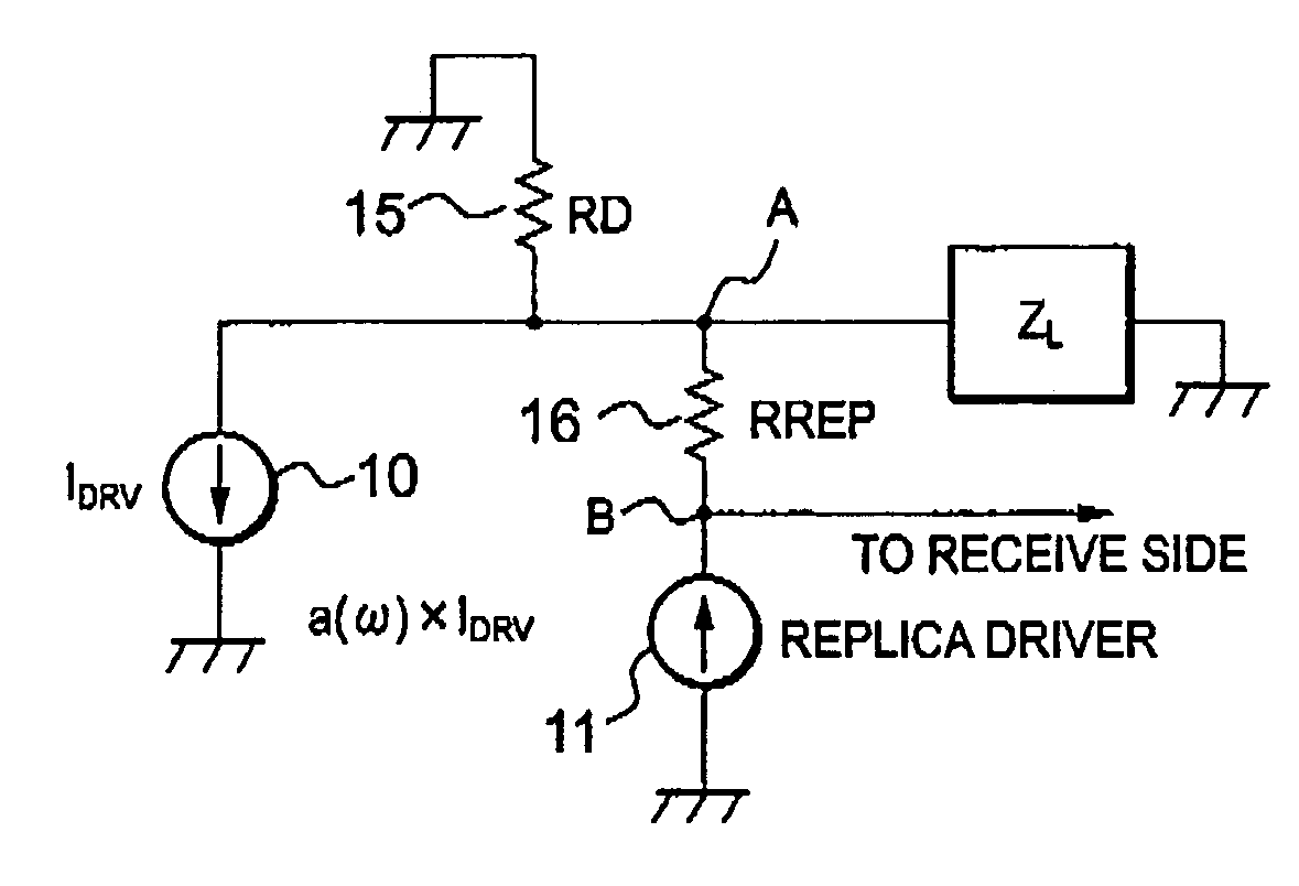
This patent describes an active hybrid transformer circuit that can operate at high speeds with low non-linear distortion. The circuit has a simple structure without any analog subtracters and can cancel out echo without using any subtracters. It uses a current driver, a load resistor, a replica driver, and a replica resistor to separate transmit and receive signals in bi-directional metallic cable communication. The current ratio between the current driver and the replica driver is represented by a complex number, which can vary to achieve desired performance. The circuit can be implemented using a DAC or a digital filter trained by a training signal. The technical effects of this invention include improved signal quality, reduced distortion, and simplified circuit design.

Problems solved by technology

However, the disclosed combination is complicated in structure and results in an increase of a size and is also not suitable for high speed communication.
However, it is practically difficult to realize such a voltage driver of a high speed and a low non-linear distortion characteristic as long as restrictions are practically imposed on a source voltage and power consumption.
According to the inventor's experimental studies, it has been found out in an active echo canceller of the above-mentioned type that an amount of attenuation is restricted to at most 10 dB on account of a component returned from the transmit signal to the receive signal and that the analog subtracter with a low non-linear distortion can not be easy to really attain.

Method used


Image

  • Active hybrid transformer circuit having a replica driver
  • Active hybrid transformer circuit having a replica driver
  • Active hybrid transformer circuit having a replica driver

Examples


embodiments

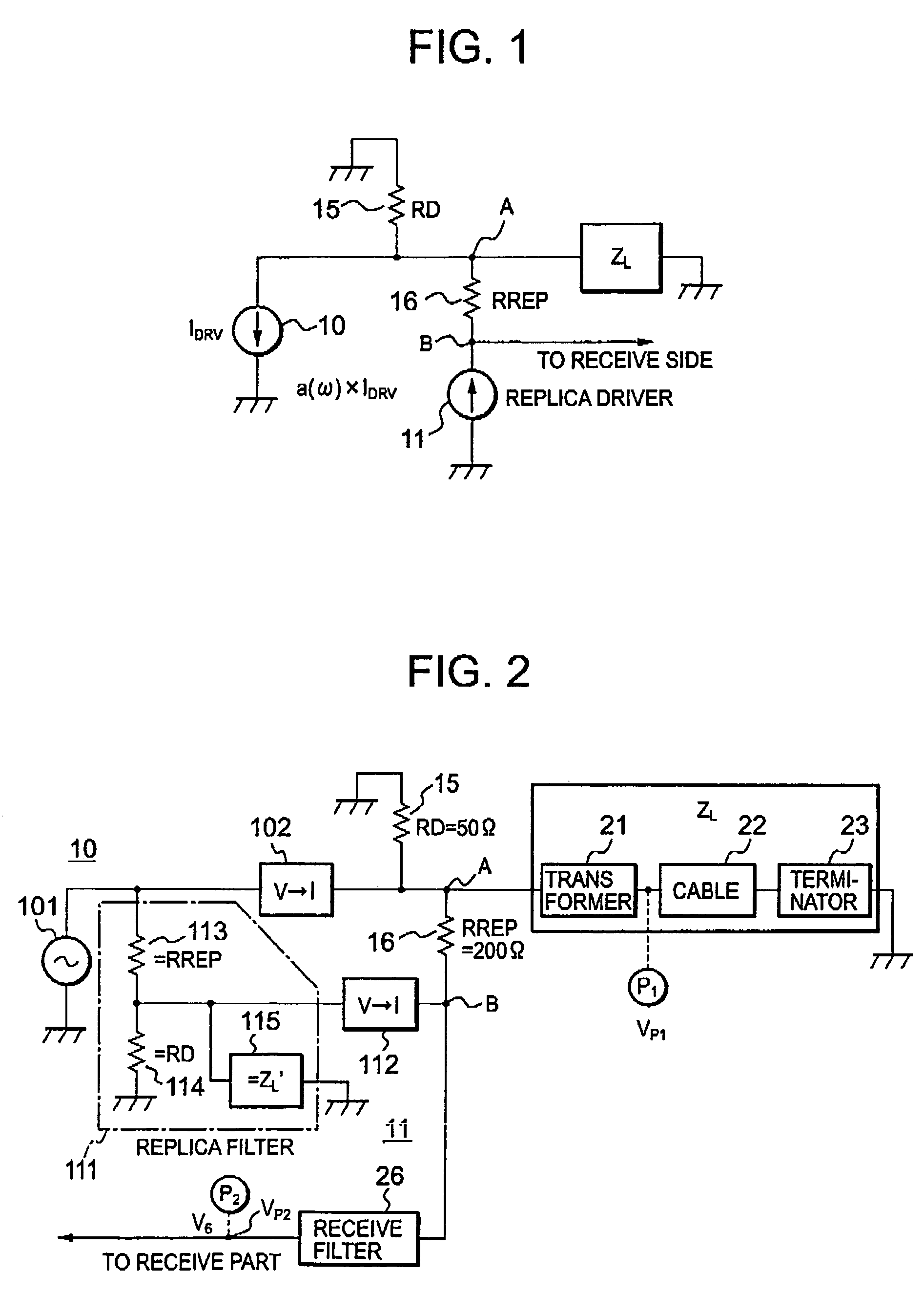
[0044]Referring to FIG. 2, an active hybrid transformer circuit according to a first embodiment of this invention is based on the above-mentioned principle and has similar parts designated by like reference numerals and symbols in FIG. 1. The illustrated active hybrid transformer circuit has a voltage driver 101 and a first voltage-to-current converter (depicted by V-I in FIG. 2) 102, both of which are operable as the current driver 10, while the replica driver 11 is constructed by a replica filter 111 and a second voltage to current converter 112. In the illustrated example, each of the current driver 10 and the replica driver 11 is thus implemented by a combination of the voltage driver and the voltage to current converter.

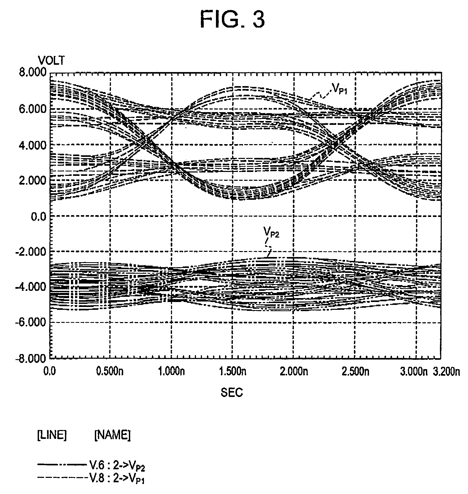
[0045]In FIG. 2, the transmission path with the impedance ZL is actually formed by a transformer 21, a cable 22, and a terminator 23. In the illustrated transmission path, a first terminal P1 is derived between the transformer 21 and the cable 22. On the other h...


PUM


Abstract

In an active hybrid transformer circuit connected to both transmit and receive sides, a current driver is connected to a transmission path circuit through a common connection point of a load resistor and a replica resistor while a replica driver is connected to the replica resistor of which another connection point is directly connected to the receive side. The replica driver may be formed by a DAC of a current output type. A current ratio of the replica driver and the current driver is selected at a predetermined value so as to prevent a transmit signal from leaking into the receive side.

Description

BACKGROUND OF THE INVENTION[0001]This invention relates to an active or adaptive hybrid transformer circuit (will be called an active hybrid transformer circuit hereinafter in the instant specification) for use in bidirectional metallic cable communication to separate a transmission or transmit (TX) signal and a reception or receive (RX) signal.[0002]A recent interest has been directed to high speed bi-directional communication trough metallic cables, such as 10 GBASE-T, among a plurality of terminal stations each of which has a transmitter / receiver connected through the metallic cables operable as a transmission path circuit. In this event, each terminal station must separate a transmit (TX) signal and a receive (RX) signal from each other so as to carry out the bi-directional communication. To this end, a hybrid transformer circuit is built in each terminal station.[0003]Conventionally, Japanese Unexamined Patent Publication No. Hei 4-54718 (namely, 54718 / 1992) discloses a combina...

Claims


Application Information

Patent Timeline
Patent Type & Authority Patents(United States)
IPC IPC(8): H03K3/00H04L25/02H03B1/00H04B3/03H04L5/14
CPCH04L5/1423H04L25/0292H04L25/028
Inventor NAGAHORI, TAKESHISUGAWARA, MITSUTOSHI
Owner RENESAS ELECTRONICS CORP
Learn More