Radar apparatus

a radar and beam forming technology, applied in the direction of instruments, measurement devices, vehicle components, etc., can solve the problems of large number of antenna elements, inability to guarantee the advantages of the conventional dbf radar apparatus in the radar apparatus, and lack of consideration of the antenna system

Active Publication Date: 2007-03-13
FUJITSU GENERAL LTD
View PDF52 Cites 29 Cited by
  • Summary
  • Abstract
  • Description
  • Claims
  • Application Information

AI Technical Summary

Benefits of technology

[0036]In contrast, the general configuration of a DBF radar resembles the radar apparatus according to the first embodiment as shown in FIG. 1. The radar apparatus according to the first embodiment uses digital signal processing to perform the function of the phase shifters of the phased array antenna radar.

Problems solved by technology

However, the advantages of the conventional DBF type radar apparatus cannot be guaranteed in these radar apparatuses.
Moreover, in these radar apparatuses, the objective was to limit the number of high frequency analog devices, and hence, the antenna system was not given much consideration.
However, in many cases, the number of antenna elements, rather than the number of high frequency analog devices, presents problems such as constraints in mounting.
Considering the size of the antenna element itself (usually about λ / 2), and the need to avoid the influence of coupling between the antenna elements, it is difficult to narrow the spacing (for example, make it less than λ) between the antenna elements of the array antenna.
Consequently, in the array antennae provided on such a radar apparatus, although the spacing between the phase centers of the two array antennae can be set below λ, the spacing between the antenna elements of the array antenna itself may be more than λ. Thus, it is impossible to effectively curb the range of ambiguity in the target direction due to the antenna pattern of the array antenna itself.
Thus, it is difficult to assemble and arrange the antenna elements of the array antennae, and the number of antenna elements has to be reduced when there are space constraints on the mounting platform.
Moreover, the degree of freedom required in controlling the beam width and the beam bearing of each array antenna is almost absent in the radar apparatus disclosed in Japanese Patent Laid-Open Publication No.
Thus, it is difficult to carry out monopulse processes involving a high degree of freedom, such as limiting the search area or substantially simultaneously searching multiple search areas.
Because considerable space is required for mounting the transmitting antennae, it is impossible to implement the system when there are space constraints on the platform used for mounting the transmitting antennae.

Method used


Image

  • Radar apparatus
  • Radar apparatus
  • Radar apparatus

Examples


first embodiment

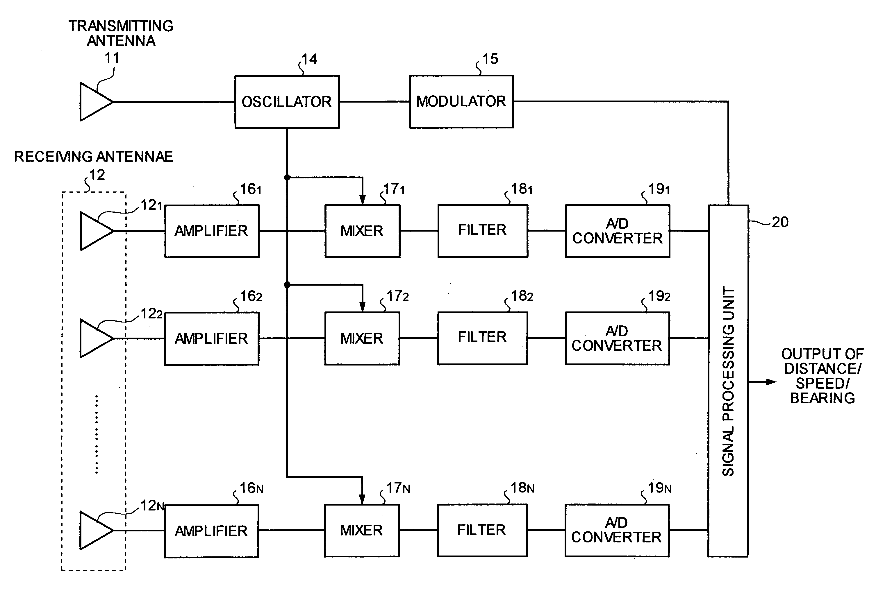
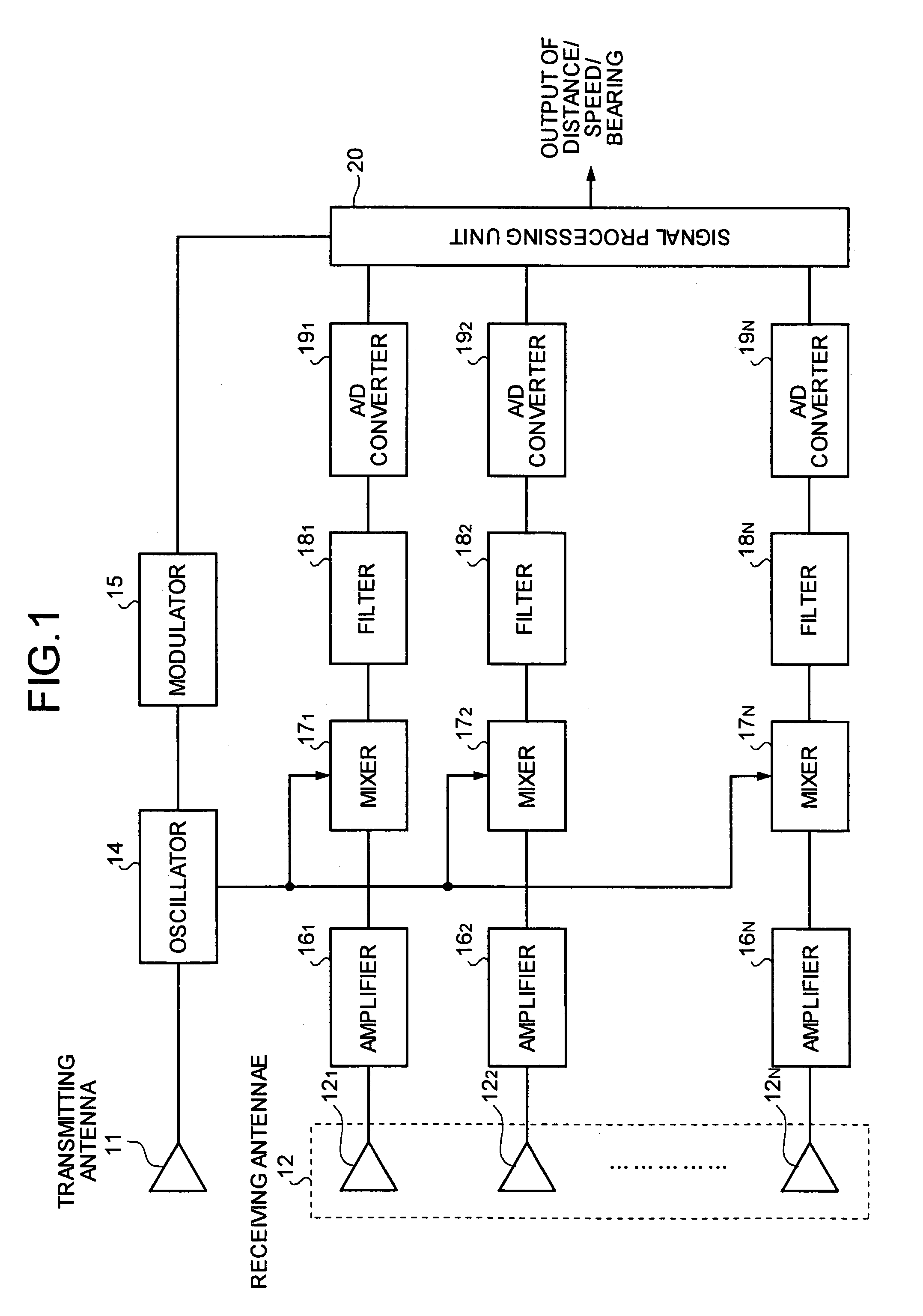
[0032]FIG. 1 is a block diagram of a radar apparatus according to the present invention. A transmitting system of the radar apparatus in FIG. 1 includes a transmitting antenna 11, an oscillator 14, and a modulator 15. A receiving system includes a plurality of receiving antennae 12 (121, 122, . . . 12N), amplifiers 16 (161, 162, . . . 16N), mixers 17 (171, 172 . . . 17N), filters 18 (181, 182, . . . 18N), A / D converters 19 (191, 192, . . . 19N), and a signal processing unit 20. The amplifiers 16 are connected to corresponding receiving antennae 12. The mixers 17 downconvert each of the signals (reception signals) output from the amplifiers 16, based on the signals (local signals) fed from the oscillator 14. The filters 18, connected to the mixers 17, put a bandwidth constraint on the downconverted signals. The A / D converters 19, connected to the filters 18, convert the reception signals from analog signals to digital signals, after the reception signals are subjected to bandwidth co...

second embodiment

[0056]Similar to the second embodiment, it is possible to use different types of sub-array structures and different process modes in the present embodiment, and obtain similar results.

[0057]FIG. 8 is a block diagram of a radar apparatus according to a third embodiment of the present invention. The radar apparatus shown in FIG. 8 includes a modulation controller 22 between the modulator 15 and the signal processing unit 20. The rest of the structure is identical to the structure according to the first embodiment shown in FIG. 1. The parts in the third embodiment that are the same as or equivalent to the parts in the first embodiment are assigned the same reference numerals.

third embodiment

[0058]When fixed objects or medium and long distance target objects are present in the direction-of the target object, or when a strong noise source is present even though not in the direction of the target object, the filters 18 may fail to filter out signals from these objects, thereby resulting in detecting a wrong object rather than the intended target. Hence, in the radar apparatus the modulation controller 22 provides control to vary various parameters of the modulated signals output from the modulator 15, based on the control exerted by the signal processing unit 20. For the FM-CW radar apparatus, the parameters of the modulated signals include frequency shift width, repetition cycle, etc. For the pulse-Doppler radar apparatus, the parameters of the modulated signals include pulse repetition frequency, pulse width, etc.

[0059]The functioning of the radar apparatus according to the third embodiment is explained next, using the FM-CW radar as an example. The principle of an FM-...


PUM


Abstract

In a radar apparatus, a receiving antenna includes a plurality of antenna elements, each receiving, as a reception signal, radio waves emitted into space and reflected off a target object. An analog signal is obtained by downconverting and putting a bandwidth constraint on the reception signal, and is then converted to a digital signal. Based on the digital signal, a signal processing unit detects the bearing of the target object. The signal processing unit performs processing based on outputs of two sets of the antenna elements.

Description

BACKGROUND OF THE INVENTION[0001]1. Field of the Invention[0002]The present invention relates to a Digital Beam Forming (DBF) radar apparatus having a receiving antenna that includes a plurality of antenna elements, and that forms antenna beams digitally.[0003]2. Description of the Related Art[0004]In recent years, DBF type radar apparatuses provided with array antennae that include a plurality of antenna elements, and that form antenna beams digitally with the aid of a signal processing unit, have come into focus.[0005]Each of the antenna elements in the array antenna is connected to a radio frequency (RF) amplifier, a mixer, a filter, and an A / D converter. A digital beam forming processor takes in digital signals that are output by each A / D converter, and carries out a digital beam forming process.[0006]Japanese Patent Laid-Open Publication Nos. H11-160423 H11-064485 disclose DBF type radar apparatuses in which the number of expensive high-frequency analog devices that are attache...

Claims


Application Information

Patent Timeline
Patent Type & Authority Patents(United States)
IPC IPC(8): G01S13/44G01S7/02G01S7/285G01S7/35G01S13/34G01S13/93
CPCG01S7/354G01S13/341G01S13/4454G01S13/4463G01S13/345G01S2007/356G01S7/356B60C19/12
Inventor ISAJI, OSAMU
Owner FUJITSU GENERAL LTD
Why Eureka
Try Eureka