Proactive predictive preventative network management technique

a network management and predictive technology, applied in the field of data network monitoring technology, can solve the problems of overwhelming network technicians, not necessarily providing the most practical solution, and a large number of alarms, and achieve the effect of easing performance degradation

Inactive Publication Date: 2007-03-13
AMERICAN TELEPHONE & TELEGRAPH CO
View PDF12 Cites 10 Cited by
  • Summary
  • Abstract
  • Description
  • Claims
  • Application Information

AI Technical Summary

Benefits of technology

[0006]Briefly, in accordance with a preferred embodiment, there is provided a method for maintaining the performance of a network, and more particularly, a data communications network, that includes at least one element, such as a router or switch for example. In accordance with the method, at least one attribute of the element is monitored periodically (e.g., hourly, daily or weekly). The monitored attribute is compared to a corresponding threshold value. Such monitoring and comparison yields an historic performance trend for the element from which a determination can be made whether the there is at least one crucial attribute of the element that warrants closer monitoring. If the closer monitoring is warranted, then the element is monitored in near real time, say every ten minutes, to determine whether a persistent performance degradation exists. If so, then the network element is altered, either by repair or replacement, to ameliorate the performance degradation. The foregoing method enables a network operator to better isolate those network elements that exhibit degraded performance, thus affording the network operator the ability to fix the trouble before the subscriber becomes aware of the problem.

Problems solved by technology

Such systems do not necessarily provide the most practical solution to the problem of monitoring network performance.
In practice, setting alarm thresholds to a low setting to track trouble signatures will yield a large number of alarms, often overwhelming network technicians.

Method used


Image

  • Proactive predictive preventative network management technique
  • Proactive predictive preventative network management technique
  • Proactive predictive preventative network management technique

Examples


Embodiment Construction

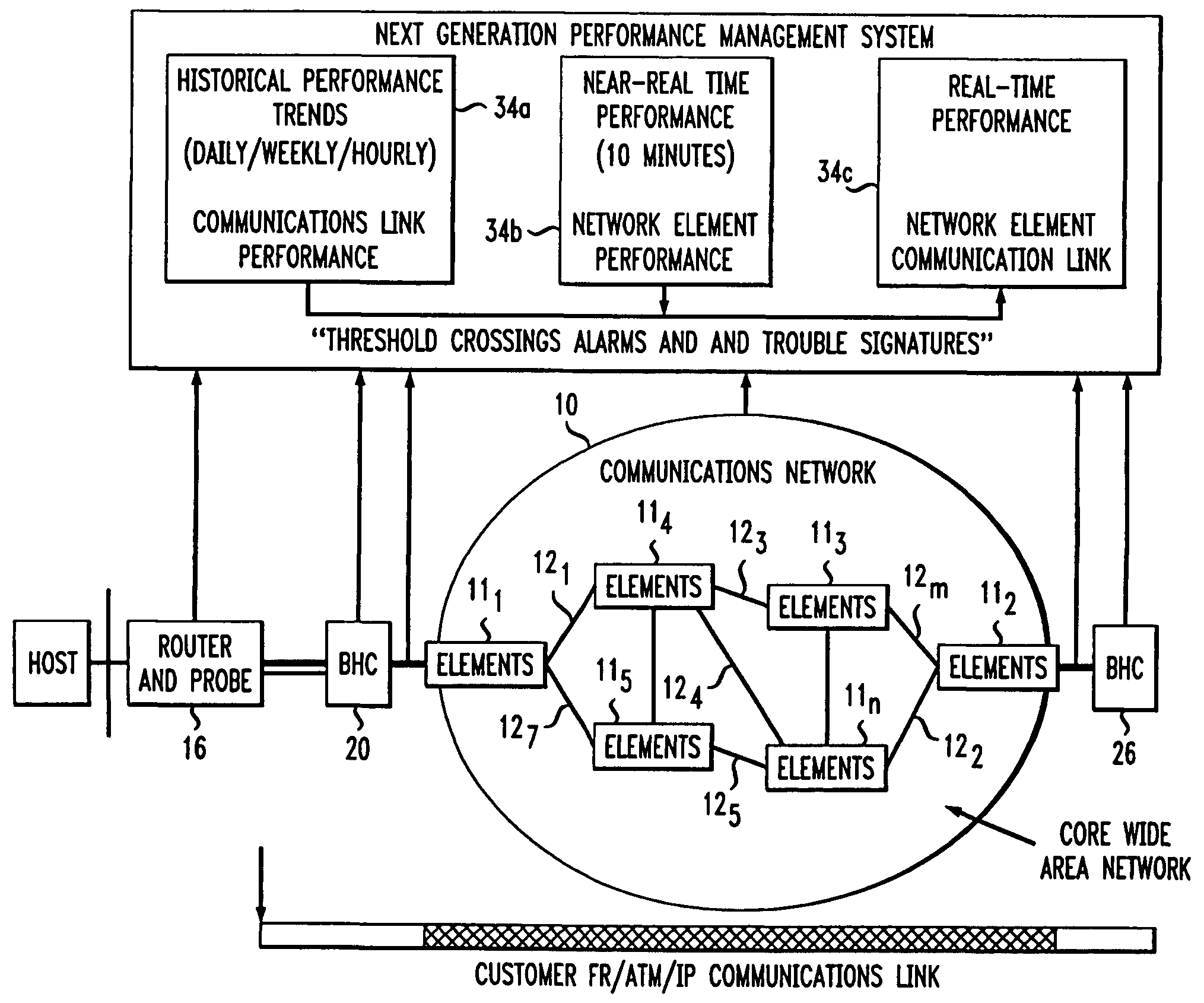
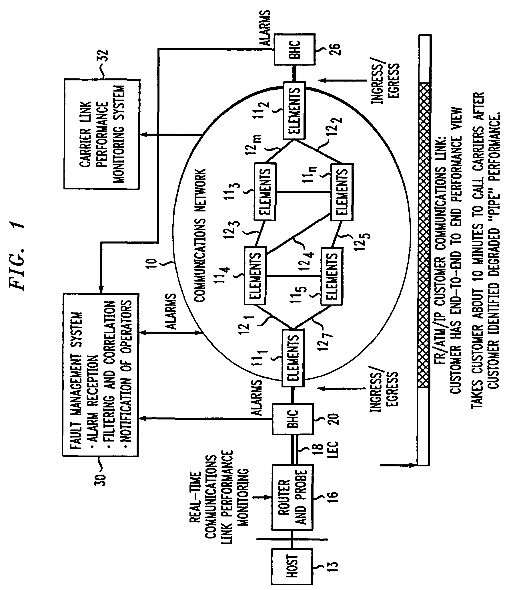
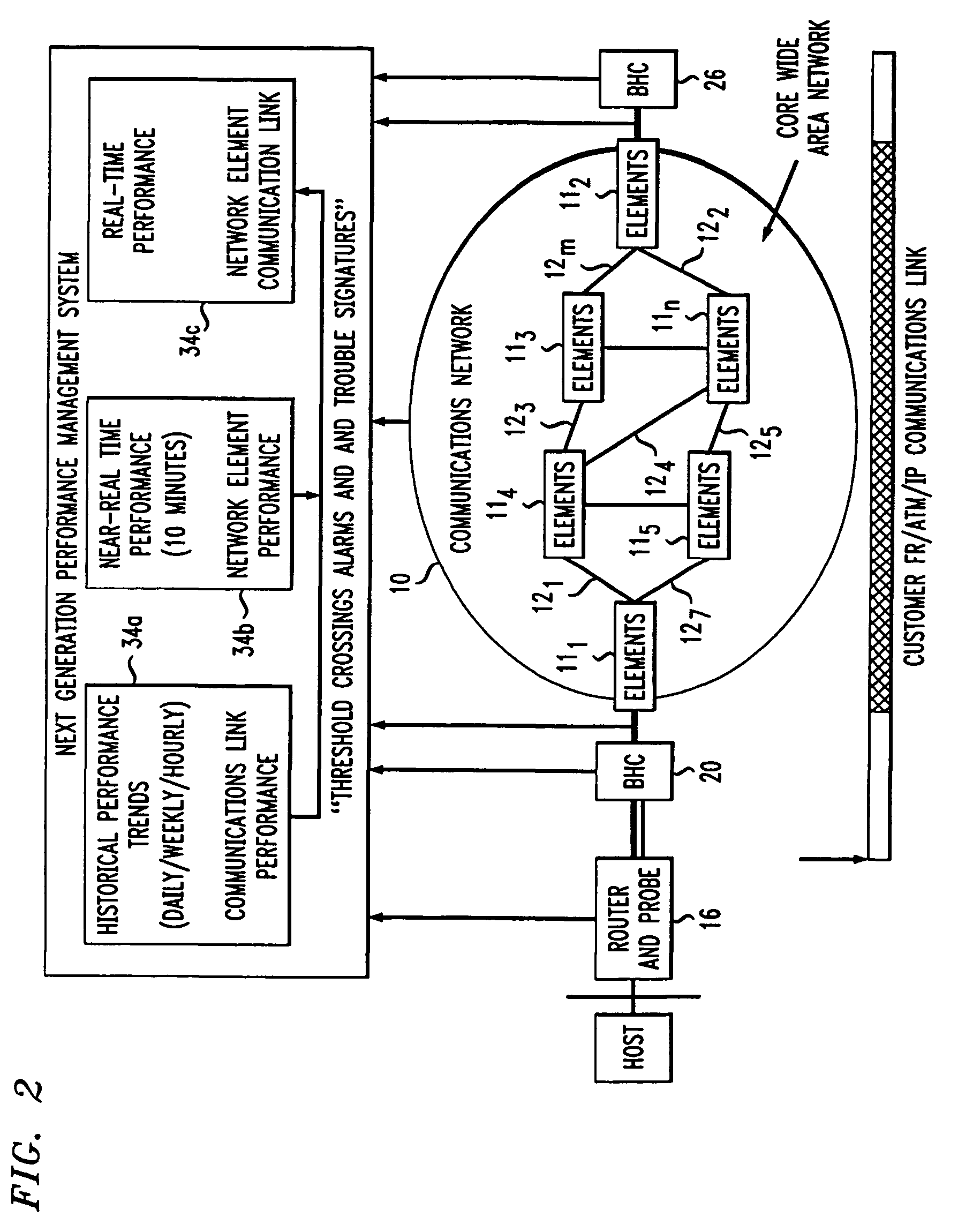
[0009]FIG. 1 depicts a communications network 10 comprised of a plurality of network elements (e.g., routers) 111–11m (where m is an integer) interconnected by links 121–12n (where n is an integer). The network 10 communicates traffic (i.e., data packets) between two or more hosts, exemplified by hosts 13 and 14. A first router 16 links the host 13 to a first Local Exchange Carrier (LEC) 18. A first Backbone-to-Horizontal Cross-connect (BHC) 22 connects the LEC 18 to router 111 within the network 10. The router 111 is “homed” to the host 13 and serves as the ingress / egress router for that host. A second router 22 links the host 14 to a second Local Exchange Carrier (LEC) 24. A second Backbone-to Horizontal Cross-connect (BHC) 26 connects the LEC 24 to router 112. The router 112 is “homed” to the host 14 and serves as the ingress / egress router for that host

[0010]In practice, the routers 16 and 22 that ultimately link the hosts 13 and 14 to the routers 111 and 112, respectively, each ...


PUM


Abstract

A next generation performance network management system (30′) includes a first component (34a) that monitors one or more attributes of network elements (111–11n, 121–12m, 20 and 26) as well as peripheral devices (16 and 22) and interconnecting links (18, 24) to establish an historic trend for each monitored element. A second performance management system component (34b) monitors, on a near real-time basis, critical attributes of elements identified from historic trends as undergoing performance degradation. If such performance degradations persist, as detected by such near real-time monitoring, then the network operator can repair or replace the element in question to maintain network performance.

Description

CROSS-REFERENCES TO RELATED APPLICATIONS[0001]This application is a continuation of U.S. patent application Ser. No. 10 / 035,306, filed 7 Nov. 2001, now U.S. Pat. No. 7,007,084 by the same inventors and similarly titled.TECHNICAL FIELD[0002]This invention relates to a technique for monitoring a data network to provide an indication of when a failure may occur.BACKGROUND ART[0003]In recent years, the needs of large telecommunications subscribers have evolved from a demand for conventional long distance service to a need for high-bandwidth data transmission capability. As the sophistication of large telecommunications subscribers has advanced, so has their capability to monitor the quality of services they receive. Many large subscribers of data communications services now have the ability to detect deviations in the quality of service they receive, often in advance of any detection by the carrier providing the service.[0004]Present-day performance monitoring systems employed by teleco...

Claims


Application Information

Patent Timeline
Patent Type & Authority Patents(United States)
IPC IPC(8): G06F15/173G06F11/00
CPCH04L41/147H04L43/16H04L43/067H04L43/0817H04L41/5035H04L41/0681H04L43/091
Inventor CHAKRAVARTI, ARVIND SESLAMBOLCHI, HOSSEINHELLSTERN, RICHARDMEDAMANA, JOHN BABU
Owner AMERICAN TELEPHONE & TELEGRAPH CO
Why Eureka
Try Eureka