Sanitary washing apparatus

Inactive Publication Date: 2007-03-20
PANASONIC CORP
View PDF45 Cites 41 Cited by
  • Summary
  • Abstract
  • Description
  • Claims
  • Application Information

AI Technical Summary

Benefits of technology

[0010]An object of the present invention is to provide a sanitary washing apparatus having a high washing stimulatory effect even at

Problems solved by technology

However, washing feelings conforming to the tastes of the plurality of users cannot be obtained merely by making the flow rates of the washing water high.
Accordingly, it is difficult to increase the flow rates of the washing water sprayed to the private parts of the users because of limitations o

Method used


Image

  • Sanitary washing apparatus
  • Sanitary washing apparatus
  • Sanitary washing apparatus

Examples


first embodiment

[0207](1) First Embodiment

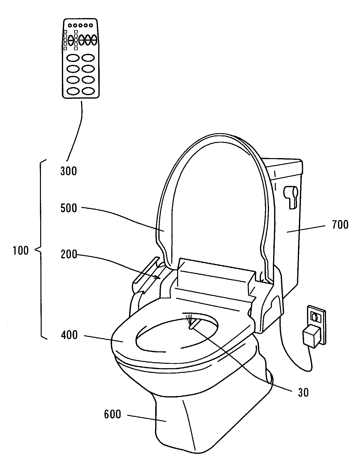
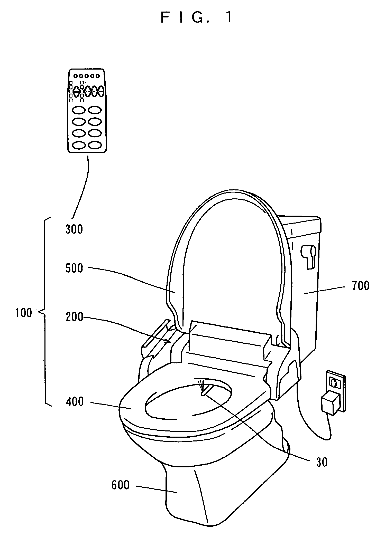
[0208]FIG. 1 is a perspective view showing a state where a sanitary washing apparatus according to a first embodiment is mounted on a toilet bowl.

[0209]As shown in FIG. 1, a sanitary washing apparatus 100 is mounted on a toilet bowl 600. A tank 700 is connected to a tap water pipe, and supplies washing water to the toilet bowl 600.

[0210]The sanitary washing apparatus 100 comprises a main body 200, a remote control device 300, a toilet seat 400, and a cover 500.

[0211]The toilet seat 400 and the cover 500 are attached to the main body 200 so as to be capable of being opened or closed. Further, the main body 200 is provided with a washing water supply mechanism including a nozzle unit 30, and contains a controller. The controller in the main body 200 controls the washing water supply mechanism on the basis of a signal transmitted by the remote control device 300, as described later. The controller in the main body 200 also controls a heater contained in the to...

second embodiment

[0346](2) Second Embodiment

[0347]Description is now made of a main body 200a in a sanitary washing apparatus 100 according to a second embodiment.

[0348]FIG. 23 is a schematic view showing the configuration of the main body 200a in the sanitary washing apparatus 100 according to the second embodiment.

[0349]The main body 200a shown in FIG. 23 differs from the main body 200 shown in FIG. 3 in that there are provided a wire 29c for changing the spray form of washing water sprayed from the posterior nozzle 1a and a motor M0 for controlling the wire 29c, and the switching valve 14 is so configured as to be switched to three flow paths, i.e., a posterior nozzle 1a, a bidet nozzle 2, and a nozzle cleaning nozzle 3. The details of the change in the spray form of the posterior nozzle 1a by the motor M0 will be described later.

[0350]FIG. 24(a) is a vertical sectional view of a switching valve 14a, FIG. 24(b) is a cross-sectional view taken along a line A—A of the switching valve 14a shown in F...

third embodiment

[0380](3) Third Embodiment

[0381]Description is now made of a main body 200b in a sanitary washing apparatus 100 according to a third embodiment.

[0382]FIG. 30 is a schematic view showing an example of the configuration of the main body 200b in the sanitary washing apparatus 100 according to the third embodiment.

[0383]The main body 200b shown in FIG. 30 differs from the main body 200 shown in FIG. 3 in that there are provided a toilet bowl cleaning nozzle 44, a switching valve 15 for switching flow paths in the toilet bowl cleaning nozzle 44 and a nozzle cleaning nozzle 3, and a motor M1 for controlling the switching valve 15.

[0384]A controller 4 rotates the motor M1 on the basis of a signal transmitted by radio from a remote control device 300 shown in FIG. 30. Consequently, the switching valve 15 supplies washing water to either one of the toilet bowl cleaning nozzle 44 and the nozzle cleaning nozzle 3 in a nozzle unit 30.

[0385]FIG. 31 is a schematic view showing how the washing wat...


PUM


Abstract

When a user sets water power using a water power adjustment switch in a remote control device, a controller controls the period of pressure fluctuations, the width of pressure fluctuations, and the central pressure of the discharge pressure of a pump on the basis of a signal transmitted by radio from the remote control device. When the user sets the divergent angle of washing water using a washing area adjustment switch in the remote control device, the controller controls the divergent angle of the washing water sprayed from a posterior nozzle on the basis of the signal transmitted by radio from the remote control device. Consequently, the washing water supplied to a side surface of a cylindrical swirl chamber from a first flow path in the posterior nozzle is sprayed from a spray hole as dispersed spiral flow, and the washing water supplied to a lower part of the cylindrical swirl chamber from a second flow path in the posterior nozzle is sprayed from the spray hole as linear flow.

Description

BACKGROUND OF THE INVENTION[0001]1. Field of the Invention[0002]The present invention relates to a sanitary washing apparatus that washes the private parts of the human body.[0003]2. Description of the Background Art[0004]Generally in sanitary washing apparatuses that wash the private parts of the human bodies, there are provided heating devices for adjusting washing water used for washing to suitable temperatures in order not to give uncomfortable feelings to the human bodies. Examples of the heating devices mainly include hot water storage type heating systems or instantaneous heating devices.[0005]The sanitary washing apparatuses using the hot water storage type heating systems comprise hot water tanks previously storing predetermined amounts of washing water as well as heating the washing water to predetermined temperatures by heaters contained therein, and employ methods of feeding by pressure the washing water previously heated to the predetermined temperatures in the hot wate...

Claims


Application Information

Patent Timeline
IPC IPC(8): A47K3/022E03D9/08
CPCE03D9/08B05B1/169B05B1/1636
Inventor MATSUMOTO, TOMOHIDEOHNO, HIDEKINAKAMURA, KAZUSHIGESHIRAI, SHIGERUFUJII, HIROAKIMARUYAMA, SHINICHITAO, MUNEO
Owner PANASONIC CORP
Why Eureka
Try Eureka