

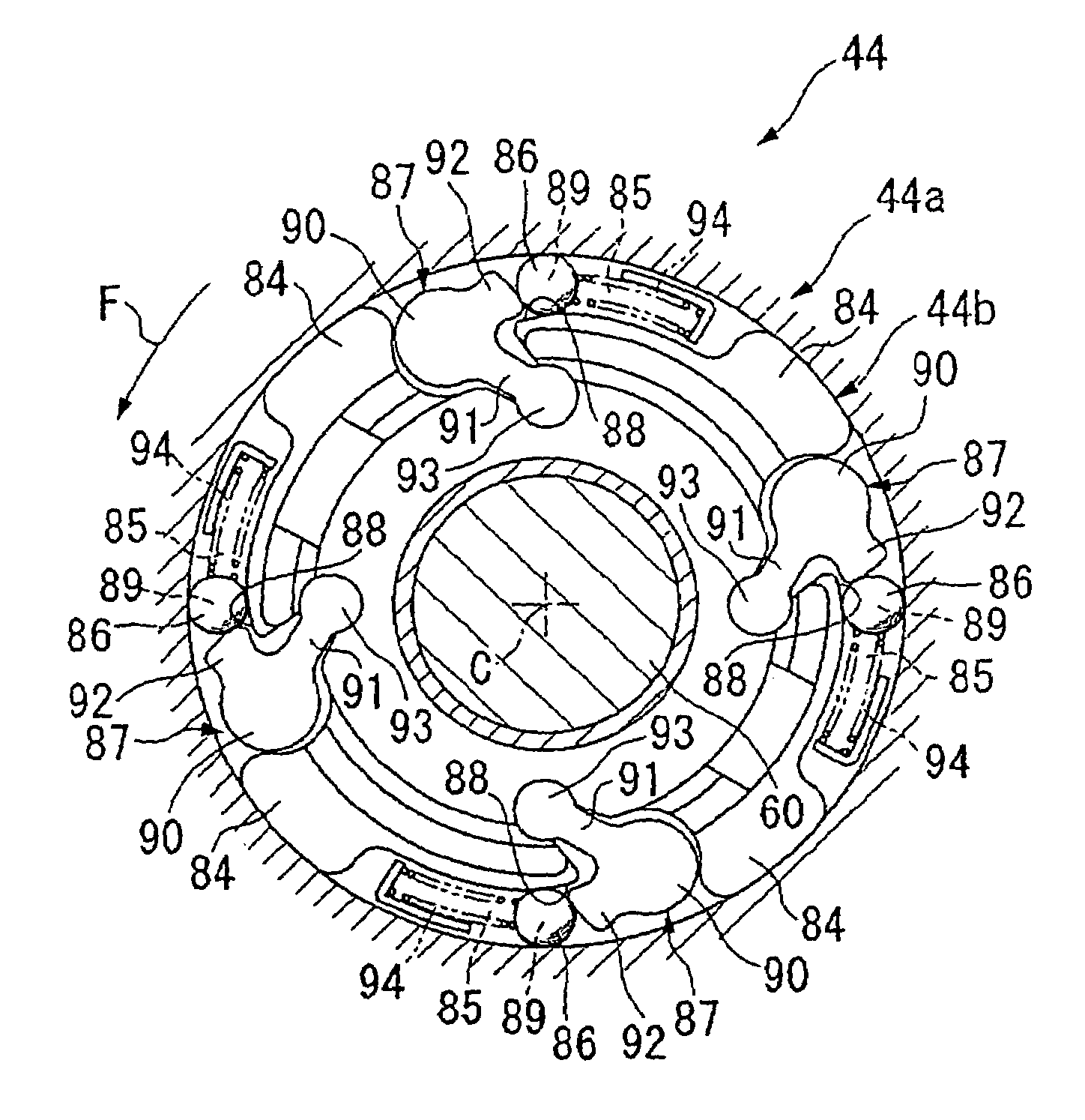
One-way clutch device and motorcycle using the same
a one-way clutch and motorcycle technology, applied in the direction of crankshaft transmission, clutch based transmission, cycle, etc., can solve the problem of complicated configuration of the one-way clutch device, and achieve the effect of improving the handleability of the motorcycle and reducing manufacturing costs
- Summary
- Abstract
- Description
- Claims
- Application Information
AI Technical Summary
Benefits of technology
Problems solved by technology
Method used
Image


Examples
Embodiment Construction
[0034]With reference to the drawings, an embodiment of the present invention will be described below. Note that, in the following description, directions such as front, rear, left and right with respect to the vehicle.
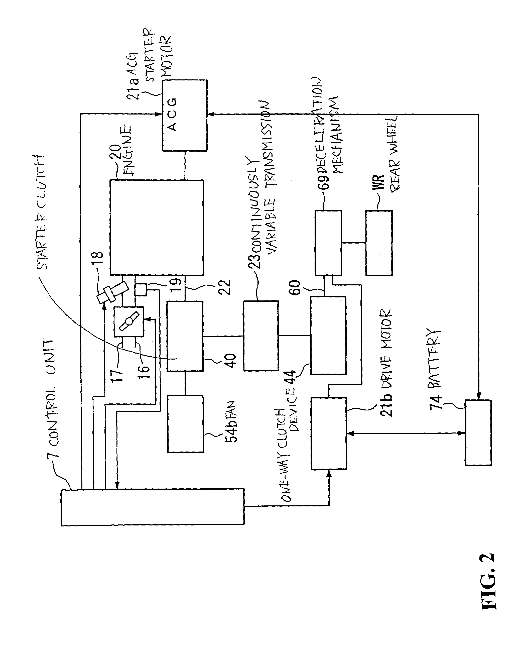
[0035]In FIG. 1, a unit swing type motorcycle 1A (hereinafter simply referred to as a motorcycle) is provided which is configured as a hybrid vehicle. This motorcycle 1A has a front fork 1 which axially supports a front wheel WF on a front side of a vehicle body. This front wheel WF and the front fork 1 are pivotally supported by a head pipe 2 so as to be steerable by operation of a handlebar 3. A down pipe 4 is attached rearwardly and downwardly from the head pipe 2. From a lower end of the down pipe 4, a mid-frame 5 extends approximately horizontally.
[0036]From a rear end of the mid-frame 5, a rear frame 6 is formed rearwardly and upwardly. In a vehicle body frame 10 thus structured, a front end part of a power unit 11 including an engine 20 to be described later, wh...
PUM
 Abstract
Description
Claims
Application Information