Progressive cavity pump/motor stator, and apparatus and method to manufacture same by electrochemical machining

a technology of progressive cavity and motor, which is applied in the direction of electrochemical machining apparatus, machines/engines, rotary piston liquid engines, etc., can solve the problems of limited precision of drive bars and electrodes, limited electrical transfer ability, and very cost-effective threaded joints, so as to reduce adverse effects, improve heat transfer, and reduce insulating effect

Active Publication Date: 2007-03-20
LEHR PRECISION
View PDF40 Cites 69 Cited by
  • Summary
  • Abstract
  • Description
  • Claims
  • Application Information

AI Technical Summary

Benefits of technology

[0012]In order to still have a compliant seal between the stator and rotor, a thin layer of constant thickness elastomer is still required. The desired inside profile of the stator, offset by the desired thickness of the elastomer layer, is formed in a circular, cylindrical inner wall of a tubular, metal workpiece serving as a stator blank. The surface finish of the inner profile must allow for bonding of the elastomer forming the profile that contacts the rotor. The constant thickness of the thin elastomer layer significantly reduces the adverse effects experienced in the case of an elastomer lining having a varying thickness. Because the elastomer layer can be relatively thin throughout, its insulating effect is also reduced, allowing for better heat transfer to the rigid metallic housing.
[0013]To achieve a surface finish suitable for bonding of the elastomer to the interior wall of the stator, a distinct ECM process is used, differing from the process described in U.S. Pat. No. 6,413,407, where a seal and a flush system were used to protect the finish of machined flutes formed by electrochemical machining of the interior of a tube for use in a petroleum cracking furnace. The machine used in the present invention is similar to that in U.S. Pat. No. 6,413,407, but the seal and flush system are eliminated, allowing controlled exposure of electrolyte to the finish-machined surface. This results in a rougher surface finish, which increases the effectiveness of the elastomer-to-metal bond. A device behind the cathode of the machine is used as a supporting guide only, instead of as a seal.
[0015]This invention addresses the problems of electrical current transmission and concentricity by using a tapered adapter similar to those used for mounting rotating cutting tools in conventional machine tools. This taper can be precision machined to improve concentricity, and the increased surface contact area reduces resistance heating of the electrical joint.

Problems solved by technology

The threaded joint is very cost effective, but is limited in its ability to transfer large amounts of electrical current from the drive tube to the cathode.
The concentricity of the drive bar and electrode is also limited in its precision, and can vary.
On the other hand, the concentricity requirement for progressive cavity pumps and motors requires more precision than is possible with a threaded joint.

Method used


Image

  • Progressive cavity pump/motor stator, and apparatus and method to manufacture same by electrochemical machining
  • Progressive cavity pump/motor stator, and apparatus and method to manufacture same by electrochemical machining
  • Progressive cavity pump/motor stator, and apparatus and method to manufacture same by electrochemical machining

Examples


Embodiment Construction

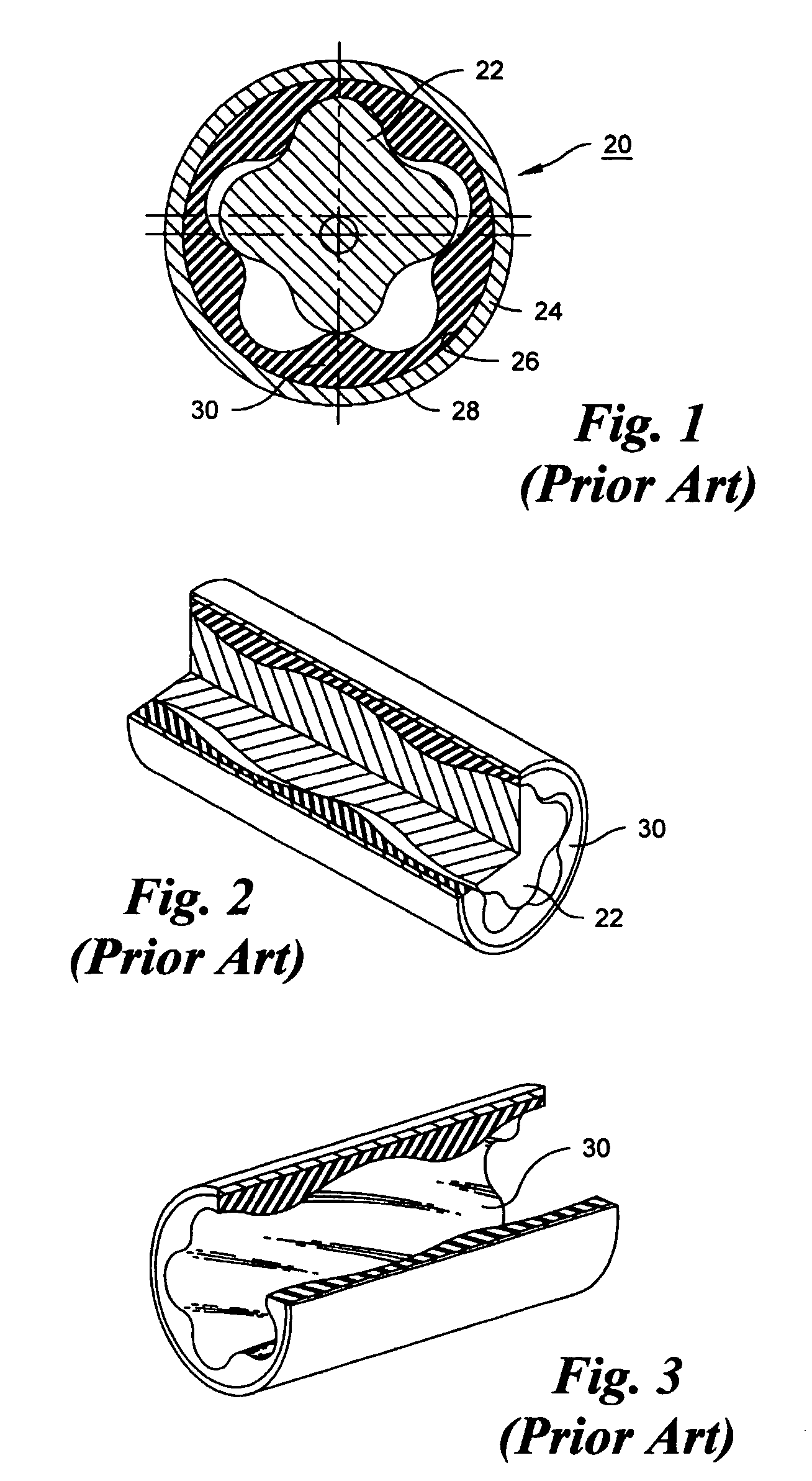
[0031]As shown in FIGS. 1–3, the conventional Moineau motor 20 comprises a helically lobed rotor 22 disposed within a stator, the stator comprising a metal tube 24 having a circular, cylindrical interior wall 26 and a circular, cylindrical exterior wall 28, the interior wall having a molded elastomer liner 30 formed with helical lobes cooperable with the rotor to provide moving fluid chambers as the rotor rotates. As seen in all three of FIGS. 1–3, the thickness of the elastomer liner varies because of the presence of the lobes.

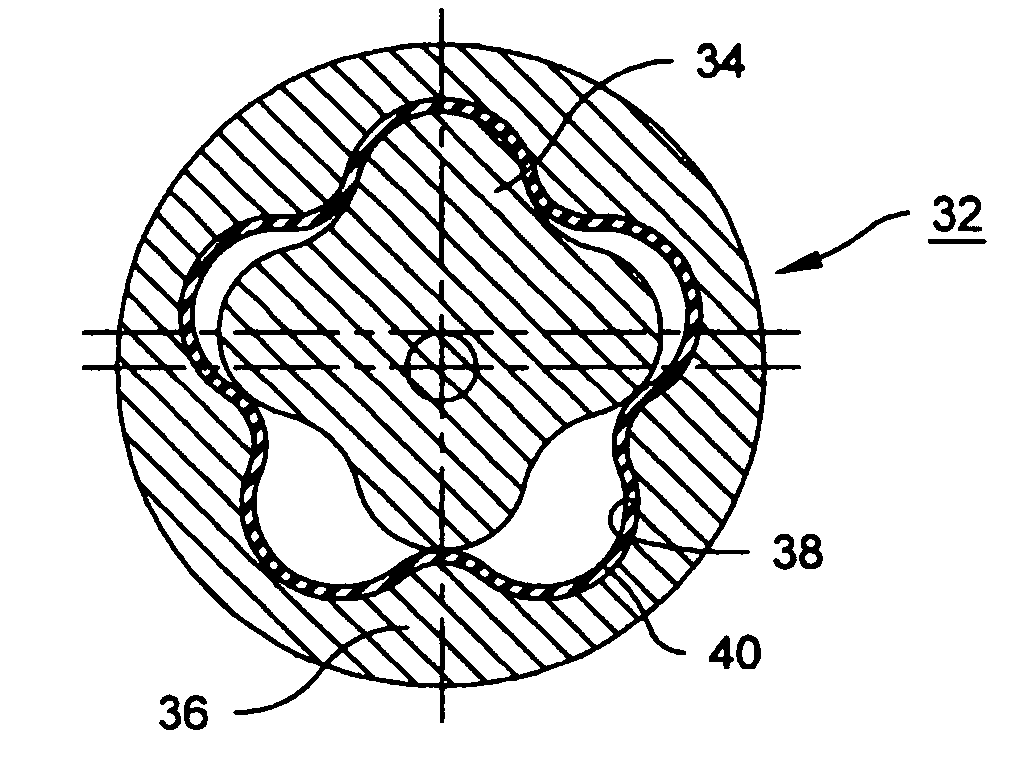
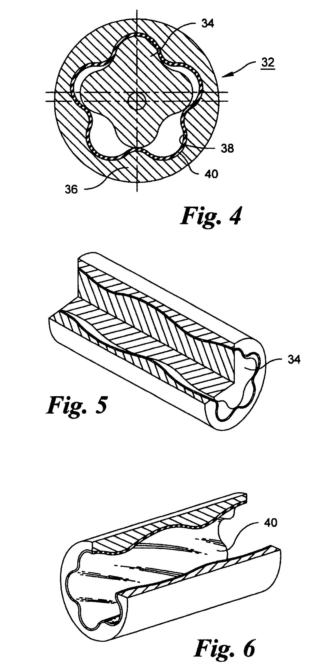
[0032]A Moineau Motor 32 in accordance with the invention, illustrated in FIGS. 4–6, comprises a helically lobed rotor 34 disposed within a stator comprising a tube 36 and a flexible liner 40. The tube 36 is composed of steel or a similar structural material. The tube has an interior wall 38 having helical lobes formed by electrochemical machining, and a circular, cylindrical exterior. Using a suitable mold or core (not shown), the molded liner 40, of rubber ...


PUM

PropertyMeasurementUnit
lengthaaaaaaaaaa
outlet pressuresaaaaaaaaaa

Abstract

Electrochemical machining is used to generate the helical lobe profiles of the stator of a progressive cavity pump or motor. A thin, elastomeric liner, of uniform thickness is bonded either to the interior of the stator, or to the exterior of the rotor. Where the elastomeric liner is to be bonded to the interior of the stator, bonding is improved by electrically etching the interior of the stator during the electrochemical machining process to produce a roughened surface.

Description

CROSS REFERENCE TO RELATED APPLICATION[0001]This application claims priority from U.S. provisional application 60 / 510,107, filed Oct. 9, 2003.FIELD OF THE INVENTION[0002]This invention relates to the manufacture of progressive cavity fluid mechanisms, that is, progressive cavity pumps and progressive cavity motors, and more particularly to a novel stator structure, and to an apparatus and process for producing the stators of such pumps and motors. The stators of progressive cavity mechanisms are typically very long, some being up to seven meters in length.BACKGROUND OF THE INVENTION[0003]U.S. Pat. Nos. 1,892,217 and 2,028,407, to R. J. L. Moineau, disclose a gear mechanism for use as a progressive cavity pump or motor. In a typical application of progressive cavity technology, the drilling of subterranean wells, a progressive cavity motor is used as a downhole motor to convert the energy of a flowing drilling fluid to mechanical power to rotate a drill bit.[0004]In a progressive cav...

Claims


Application Information

Patent Timeline
Patent Type & Authority Patents(United States)
IPC IPC(8): F03C2/08B23H3/00B23H9/00F04C2/107
CPCB23H3/00B23H9/00B23H9/005F04C2/1075Y10T29/49242F04C2230/101Y10T29/49272
Inventor LIEVESTRO, TERRYREYNOLDS, JOHNCHAMBERLAIN, TOM
Owner LEHR PRECISION
Why Eureka
Try Eureka