Parallel lamps with instant program start electronic ballast

a technology of electronic ballast and parallel lamps, which is applied in the direction of electric ignition installation, mechanical equipment, machines/engines, etc., can solve the problems of delay, drawback, and not being able to detect the delay, and still providing current to heat the cathod

Inactive Publication Date: 2007-03-20
GENERAL ELECTRIC CO
View PDF16 Cites 16 Cited by
  • Summary
  • Abstract
  • Description
  • Claims
  • Application Information

AI Technical Summary

Problems solved by technology

Despite its advantages, the program start electronic ballast does have drawbacks.
First, because it has to pre-heat the cathode before it strikes the lamp, there is a noticeable delay from the time when the light switch is activated to the time when the lamp emits visible light.
This delay is therefore a drawback in settings where a user expects an almost instantaneous lighting of an area.
Another drawback of the program start ballast is that once the lamp is lit, current is still provided to heat the cathodes when it is no longer needed.
This current is wasted, as it neither provides extra light, nor extends the life of the lamp.
This waste of power after the lamp is lit makes the system less efficient overall.
Thus, the lamps in the ballast produce no light where they could be producing light from other lamps if the lamps were in a parallel configuration.
Since all lamps will not be producing light, more frequent servicing of the lighting installation will be required, increasing the cost of labor to maintain the system.
This type of control adds to the cost of the ballast.
The second common type of ballast, the instant start ballast, addresses some issues of the program start ballast, however, it introduces some new issues of its own.
Instant start ballasts also use parallel lamp configurations with inherently built-in redundancy in the event of the lamp failure.
However, the instant start ballast produces a glow discharge current, which degrades the integrity of the cathodes during the brief period before the lamp strikes.
Over time, with instant starts, the cathodes degrade at a rate, leading to an early failure of the lamp.
Thus, a drawback of the instant start ballast is premature lamp failure.
Because an instant start ballast burns through cathodes so quickly, lamps may fail long before their expected lifetimes.
While the program start ballasts are inefficient because they waste power, the instant start ballasts are inefficient because they may require more lamps for a given amount of time.

Method used


Image

  • Parallel lamps with instant program start electronic ballast
  • Parallel lamps with instant program start electronic ballast
  • Parallel lamps with instant program start electronic ballast

Examples


Embodiment Construction

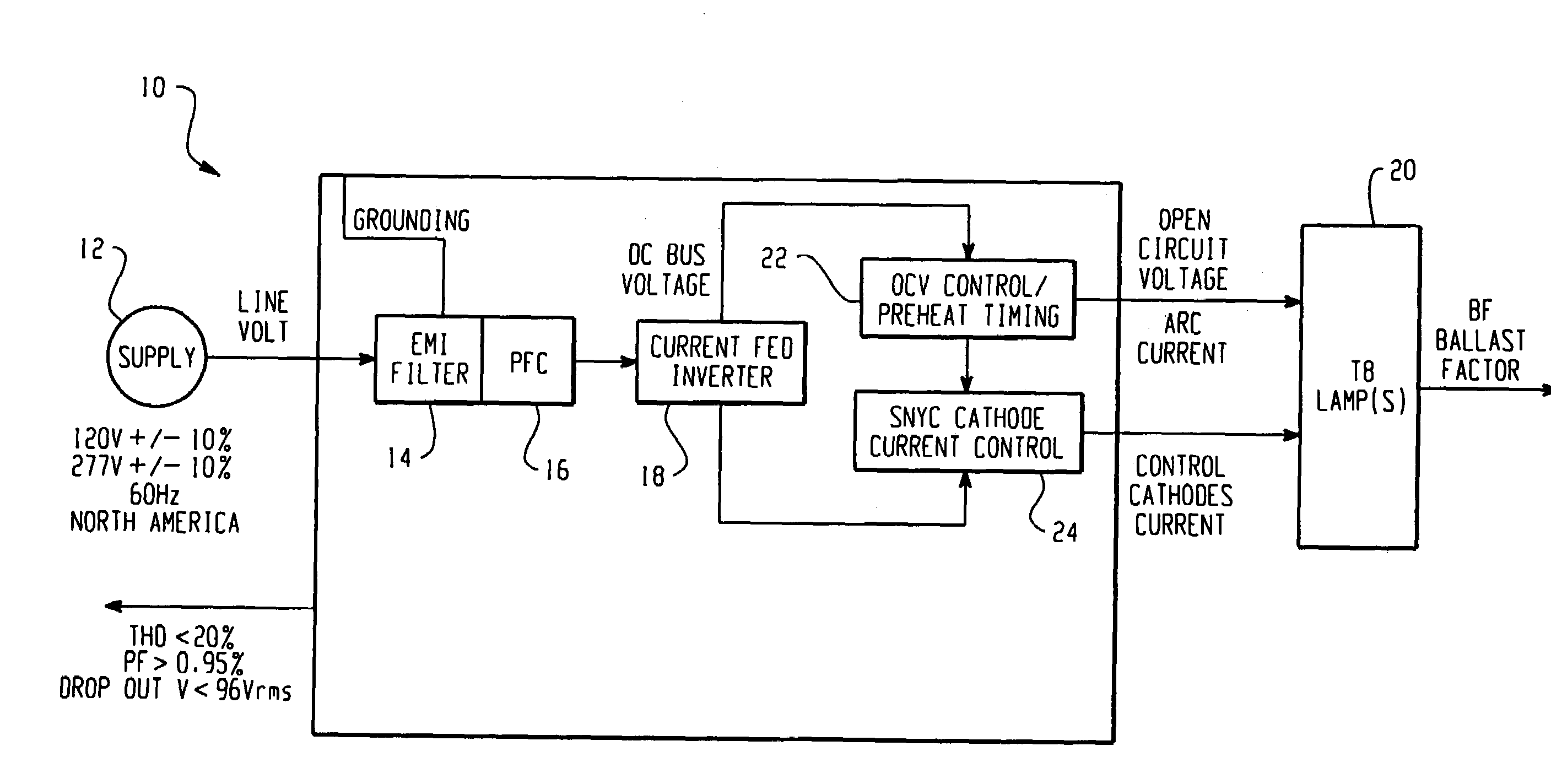
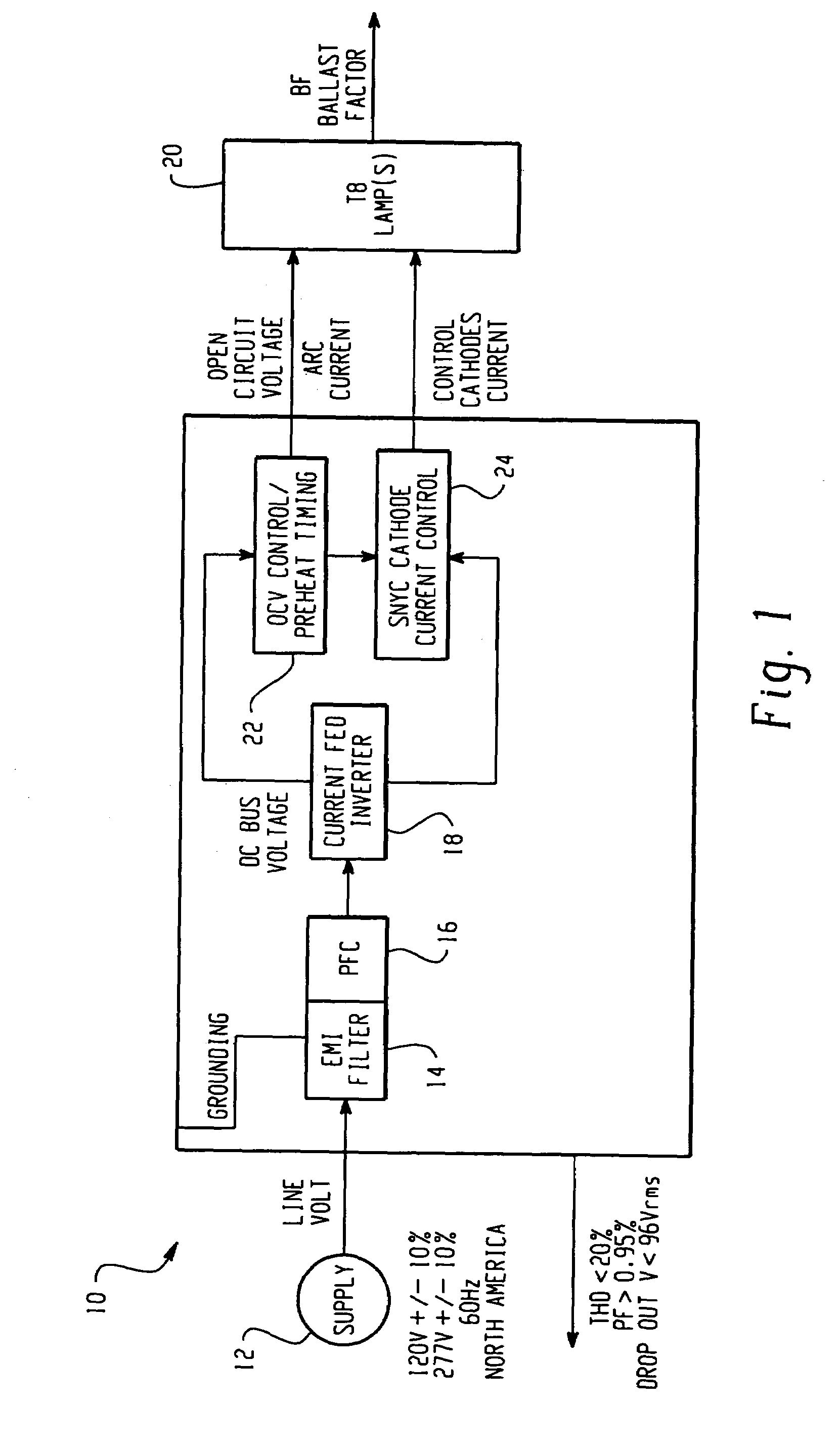
[0026]With reference to FIG. 1, a block diagram of one embodiment of a lamp ballast 10 according to the present application is depicted. A voltage supply 12 provides an AC signal to the ballast 10. The voltage supply 12 can provide a wide range of input voltages, such as 120 V, or 277 V, as is typical for the United States. The line voltage signal is filtered by an EMI filter 14 and then is converted from AC to a DC bus signal by a power factor correction circuit (PFC) 16. The power factor correction circuit 16 supplies the DC bus signal to an inverter circuit 18, which may be a current fed inverter and which generates an AC signal for the powering of lamps 20. This design permits a parallel lamp arrangement without multiple inverters or multiple ballasts. In certain embodiments the power factor correction circuit 16 will make the ballast input line current distortion low, for example, less than 10% for a 120 volt input and less than 20% for a 277 volt input. It is to be appreciated...


PUM


Abstract

In a current fed electronic ballast multiple lamps are operated in a parallel circuit arrangement. The ballast provides pre-heating to the cathodes of the lamps for a period of time before an open circuit voltage is ramped up to the preferred starting voltage of the lamps. An open circuit voltage controller times coordinates the pre-heating and the operating voltage. After the pre-heating phase, current is removed from the cathodes of the lamps so that electricity is not wasted to the cathodes while the lamps are lit. A single switch is used to switch cathode pre-heating on and off, regardless of how many lamps the ballast operates. A decoupling array of diodes allows the single switch to coordinate pre-heating to all the lamps.

Description

BACKGROUND[0001]Generally, there are two main types of fluorescent ballasts manufactured for low pressure, hot cathode discharge lamps. The first type is a hot start electronic ballast, also known as a program start electronic ballast. Typically, a program start electronic ballast provides a relatively low voltage across the lamp with a separate cathode heating current during lamp startup. Pre-heating the cathode before lamp ignition, lowers the amount of voltage needed to strike the lamp, that is, the glow discharge current is minimized. By minimizing the glow discharge current, the cathode life is extended since the amount of the cathode that is spattering off during lamp startup is minimized, extending the overall life of the lamp.[0002]This type of lighting system finds particularly useful application in a setting where the lights are frequently turned on and off, such as in a conference room, a lavatory, or other setting that sees frequent but non-continuous usage. In these set...

Claims


Application Information

Patent Timeline
Patent Type & Authority Patents(United States)
IPC IPC(8): H05B39/00H05B37/02H05B39/04H05B41/14
CPCH05B41/295
Inventor CHEN, TIMOTHYSKULLY, JAMES K.
Owner GENERAL ELECTRIC CO
Why Eureka
Try Eureka