System and method for the measurement of full relative position and orientation of objects

a technology of object relative position and measurement method, applied in direction controllers, instruments, using reradiation, etc., can solve the problems of large amount of power required for their operation, large amount of printed or placed antenna based sensors, and inability to meet the requirements of munitions applications

Inactive Publication Date: 2007-03-20
UNITED STATES OF AMERICA THE AS REPRESENTED BY THE SEC OF THE ARMY
View PDF14 Cites 30 Cited by
  • Summary
  • Abstract
  • Description
  • Claims
  • Application Information

AI Technical Summary

Benefits of technology

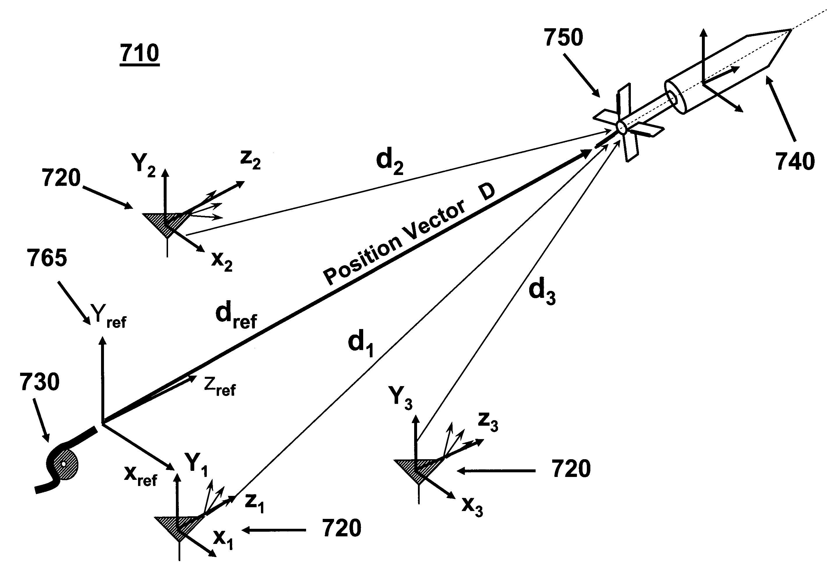
[0011]The development of an autonomous onboard absolute position and orientation measuring system (sensors) of the present invention fills this need by providing a means of determining the position and orientation of an object in flight with reference to a ground station or another mobile platform. It provides a means of efficaciously and economically embedding position and orientation measuring sensors for guidance and control p

Problems solved by technology

The surface printed or placed antennas are, however, not suitable for munitions applications since they cannot survive the firing environment and readily loose their accuracy.
Such surface printed or placed antenna based sensors also require large amount of power for their operation, and are very sensitive to geometrical variations and tolerances.
However, the inertia based sensors are relatively complex and inaccurate, occupy a considerable amount of volume, consume a large amount of power, are prone to drift and settling problems, and are relatively costly

Method used


Image

  • System and method for the measurement of full relative position and orientation of objects
  • System and method for the measurement of full relative position and orientation of objects
  • System and method for the measurement of full relative position and orientation of objects

Examples


Embodiment Construction

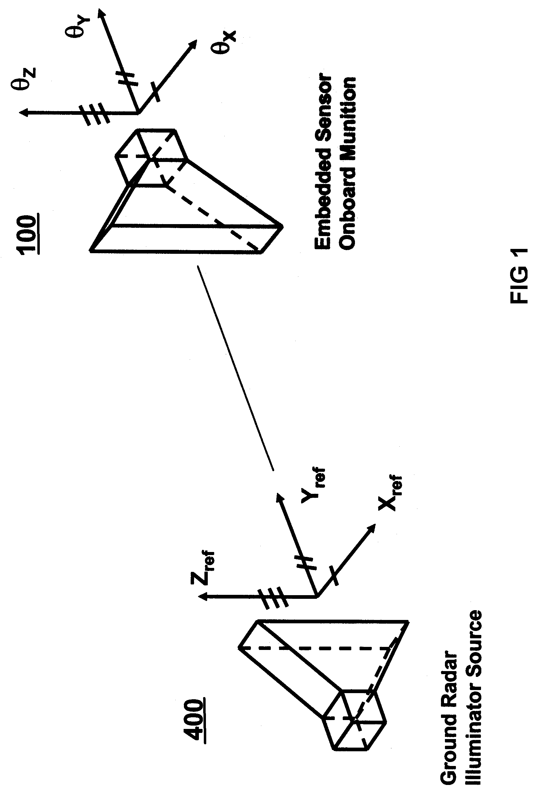
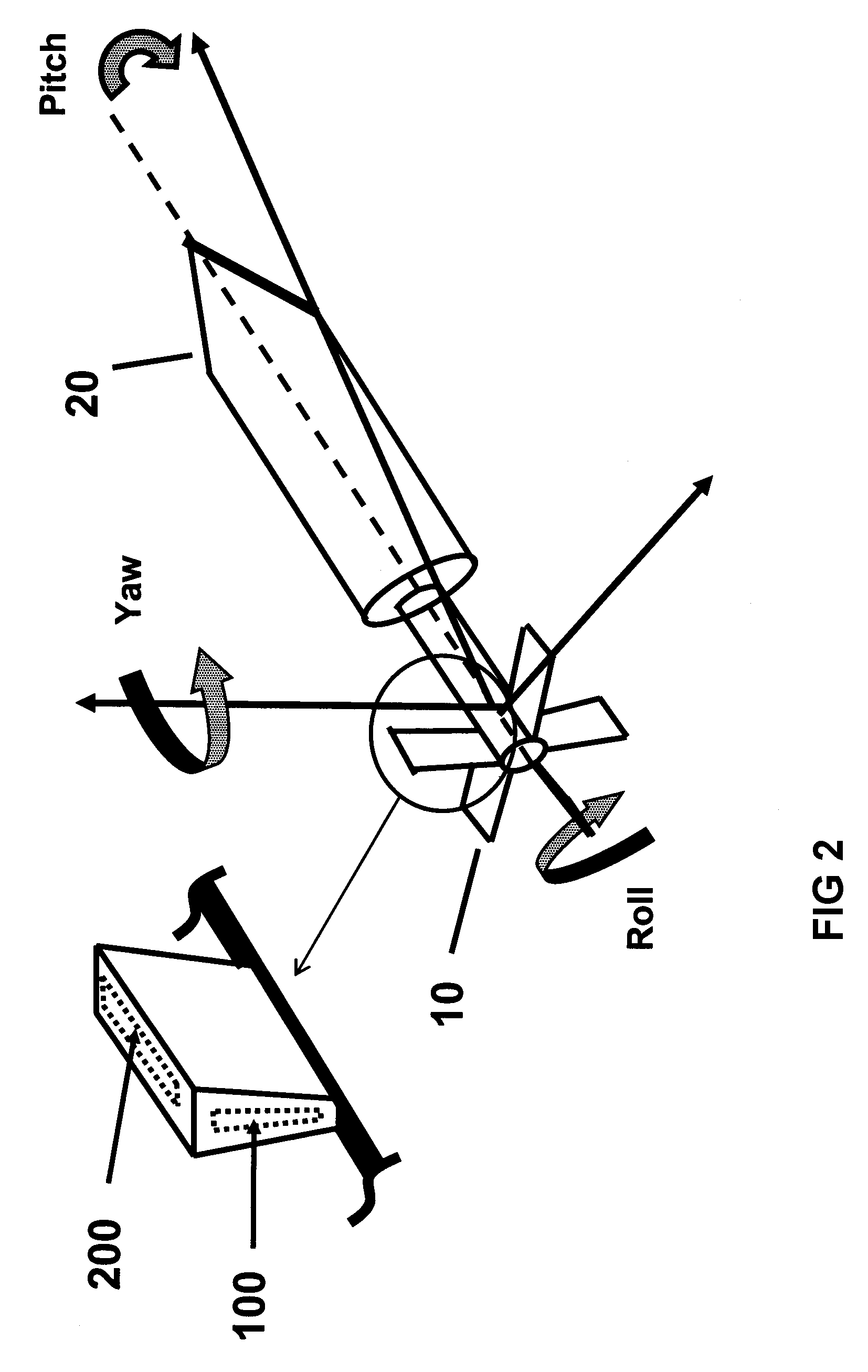
[0036]FIGS. 1 and 2 illustrate an autonomous onboard position and orientation measurement system (hereinafter also referred to as “position and orientation sensor”) 10 for an object (in this case a munition) 20. The present invention has particular utility where the object is a munition for tracking such munition during flight. However, those skilled in the art will appreciate that the system and methods of the present invention are useful with other types of objects, for example for onboard measurement of the position and orientation of a mobile robotic platform relative to the ground (for a fixed illuminating source) or another mobile robotic platform (on which the illuminating source is affixed) for navigational purposes; for measurement of full position and orientation of a vehicle as being tested for suspension performance, and in general, in any system or device in which the position and orientation of the system or device is to be measured relative to a fixed (ground) or movi...


PUM


Abstract

A system for measuring a position and orientation of an object in flight relative to a reference coordinate system is provided. The system including: three or more illuminating sources, each disposed in a predefined position, the three or more illuminating sources together emitting a plurality of distinct polarized radio frequency signals to provide temporally synchronized, pulsed radio frequency signals that illuminate the object; one or more waveguide cavities disposed on the object for receiving the plurality of distinct polarized radio frequency signals from each of the three or more illuminating sources in flight; and a processor for measuring a time for the plurality of distinct polarized radio frequency signals to propagate from each of the three or more illuminating sources to the one or more waveguide cavities and the level of signal received at the waveguide cavities and to determine a position of the object relative to the three or more illuminating sources based on the measured times and the orientation of the object relative to the reference coordinate system based on the measure levels of received signals.

Description

CROSS REFERENCE TO RELATED APPLICATIONS[0001]The present application is a continuation-in-part of U.S. patent application, titled “Autonomous Onboard Absolute Position And Orientation Referencing System,” Ser. No. 10 / 065,023, filed on Sep. 11, 2002 now U.S. Pat. No. 6,724,341, which is incorporated herein by reference.FEDERAL RESEARCH STATEMENT[0002]The invention described herein may be manufactured and used by or for the Government of the United States for governmental purposes without the payment of any royalties thereon.BACKGROUND OF INVENTION[0003]The present invention relates to systems (sensors) designed to measure full angular orientation and position of an object relative to another object. In munitions and other similar applications, such a system provides an absolute onboard referencing system, in which the munitions is provided by its full position and orientation information relative to one or more ground stations or other mobile platforms during the flight. In munitions...

Claims


Application Information

Patent Timeline
IPC IPC(8): F42B15/01F41G7/00G01S13/00
CPCF42B15/01G01S5/0247F41G7/34G01S5/14G01S7/024
Inventor PEREIRA, CARLOS M.RASTEGAR, JAHANGIR S.
Owner UNITED STATES OF AMERICA THE AS REPRESENTED BY THE SEC OF THE ARMY
Why Eureka
Try Eureka