Phase controlled antennae for data transmission between mobile devices

a mobile device and phase control technology, applied in the direction of antennas, antenna adaptation in movable bodies, instruments, etc., can solve the problems of limited extent of phase-controlled directional antennas, mechanically pivotable or phase-controlled directional antennas, and complex phase-controlled directional antennas, so as to reduce the localization of the antenna, reduce the localization of the ground, and reduce the effect of antenna localization

Active Publication Date: 2007-03-20
AIRBUS DEFENCE & SPACE
View PDF11 Cites 4 Cited by
  • Summary
  • Abstract
  • Description
  • Claims
  • Application Information

AI Technical Summary

Benefits of technology

[0006]The object of this invention is therefore to design a phase-controlled antenna for installation in the area of an exterior surface of a mobile device, preferably a flying device, which avoids the aforementioned disadvantages of the known prior art, is characterized by a simplified design and electric control and can be designed to be more compact with regard to the planar extent without any restriction on the electric specifications.
[0007]In addition to the easy integrability into existing structures of mobile devices, the special advantage of the inventive phase-controlled antenna is also the small amount of space required in the plane in which the antenna elements are arranged. It is advantageous that only a small number of individual antenna elements is needed in a plane in comparison with the prior art. In addition, it is advantageous that two or more planes having a similar arrangement of antenna elements one above the other produce an additional improvement in the directional effect and thus increase the antenna gain in the elevation direction. With high-frequency signals it is advantageous that only the central active antenna element receives signals, whereas the alignment in the elevation direction and in the azimuthal direction is accomplished exclusively by control signals with the help of which the electrically active length of the passive antenna elements is varied. This eliminates the complex networks which are necessary in the conventional prior art for supplying signals in the correct phase sequence to individual antenna elements.
[0008]If the antenna is used for reception, it is advantageous that the efficiency of the antenna is high because there are no distribution networks or phase shifter networks whose losses would reduce the efficiency.
[0010]The controlled adjustment of the phase effect of the individual passive antenna elements is accomplished easily by connecting or disconnecting and / or bridging the passive components (such as capacitors or inductors), by connecting or disconnecting controllable components (such as variable capacitance diodes or variometers) and by connecting lines. Control of the controllable components may be accomplished by analog or digital means using D / A converters.
[0011]To improve the directional effect in the elevation direction, two or more planes with the same groups of active and passive antenna elements are advantageously arranged one above the other with a distance of at least one-third of the operating wavelength being maintained between the ends of the antenna elements of different levels. The antenna diagram of the overall arrangement of the phase-controlled antennas in the elevation direction is advantageously accomplished by individual control of each plane with regard to the absolute value and phase of the signal. The distance between two levels should amount to at least ¾λ of the operating wavelength.
[0015]Because of the compact dimensions, the radar localizability of the antenna is also reduced. Thus in the case of flying devices, defensive measures (e.g., flare jammers) against threats from the ground may also be greatly reduced. Furthermore, the localizability from the ground is reduced because signals are emitted only in the direction of the remote station. Because of the good bundling in the azimuth and elevation, the localizability from the ground is reduced because of the lower required transmission power, and because signals are emitted only in the direction of the remote station. This reduces the electric power to be supplied.

Problems solved by technology

The use of mechanically pivotable or phase-controlled directional antennas, usually covered with large radomes, is possible only to a limited extent because of the considerable amount of space required, e.g., in compact flying devices.
However, phase-controlled directional antennas are very complex because of the large number of component antennas required and because each component antenna must be triggered in a phase-controlled and amplitude controlled manner.
This antenna is designed for the same intended application but it requires a great complexity of components for controlling the individual active antenna elements because of the many antenna components which must be triggered in a phase-controlled and amplitude-controlled procedure.
This type of antenna has an extremely broad band but controlled adjustability of the directional effect is limited, particularly in the elevation direction.
This reduces the electric power to be supplied.

Method used


Image

  • Phase controlled antennae for data transmission between mobile devices
  • Phase controlled antennae for data transmission between mobile devices
  • Phase controlled antennae for data transmission between mobile devices

Examples


Embodiment Construction

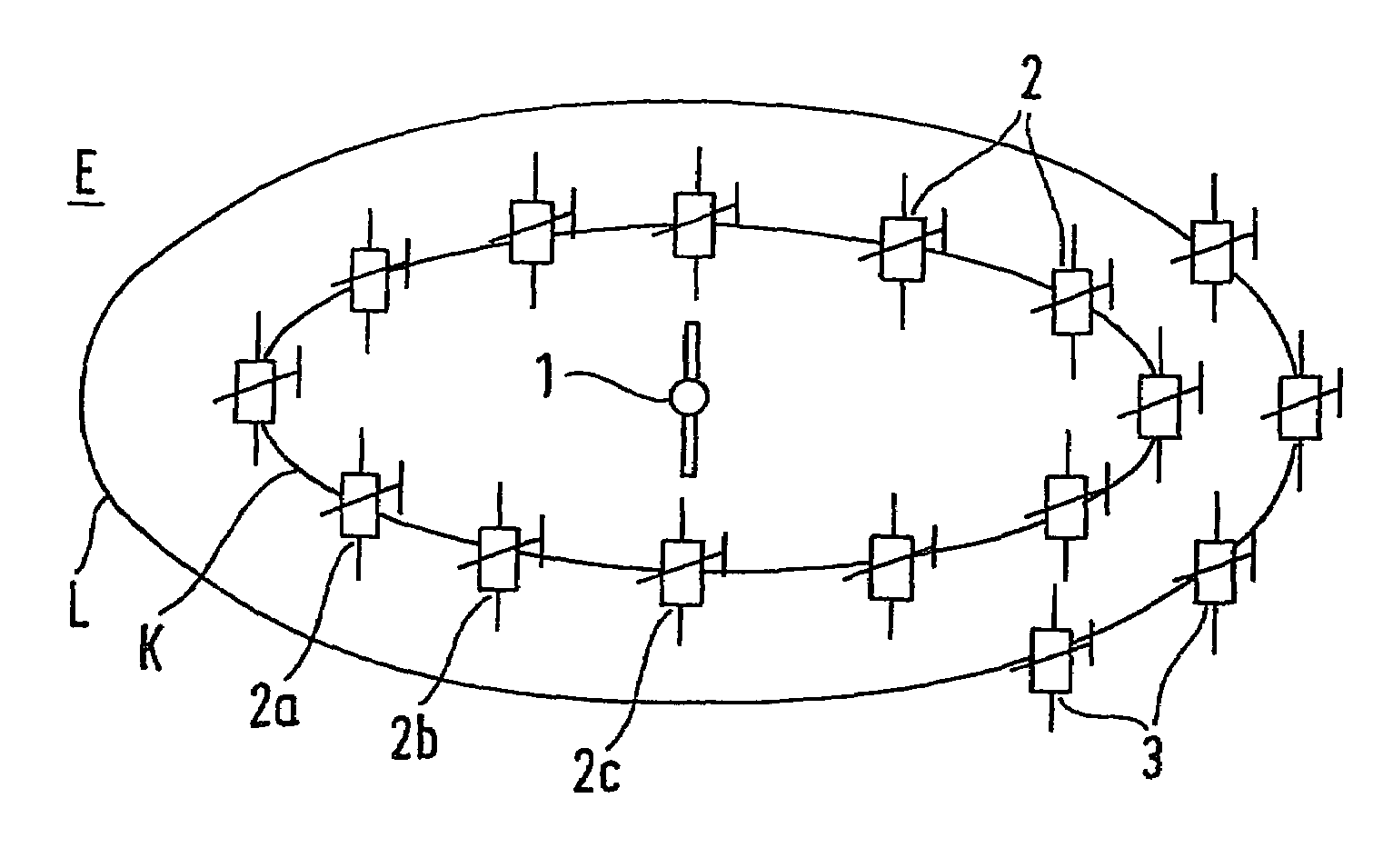
[0028]FIG. 1 illustrates an inventive phase-controlled antenna which is arranged in a plane spanned by the circles K and L and which extends approximately parallel to the longitudinal axis of a mobile device (which is not shown in greater detail here), in particular a flying device. The term longitudinal axis as used here is understood to refer to the main direction of movement of the respective device. Thus the plane E may be aligned preferably approximately horizontally or even vertically as well as in any intermediate position between the aforementioned positions.

[0029]A group of passive antenna elements 2, 2a, . . . , 2c is placed at least on an imaginary circle K around a centrally arranged active antenna element 1. The radius of the imaginary circle is a multiple n of a quarter of the operating wavelength λ where n=1, 2, 3, . . . The group may be designed so that it includes a small number of antenna elements 2a, 2b, 2c arranged with a distance between them (forming a “group” ...


PUM


Abstract

In a phase-controlled antenna array for mobile devices, in particular designed for flying device, groups of controllable passive antenna elements are arranged in concentric circles around an active central antenna element. The arrangement of additional similar planar antenna arrays among the original antenna array is especially advantageous with regard to bundling the emission characteristic.

Description

BACKGROUND AND SUMMARY OF THE INVENTION[0001]This application claims the priority of German Patent Application 103 35 216.3, filed Aug. 1, 2003, the disclosure of which is expressly incorporated by reference herein.[0002]This invention relates to a phase-controlled antenna comprising a plurality of antenna elements situated in the area of the surface of a mobile device.[0003]Trackable bundled antennas are required for transmission of large data volumes over great distances between unmanned flying devices, airplanes, motor vehicles and stationary stations. These antennas can automatically align themselves with the remote station in accordance with the rate of propagation of the respective device.[0004]The use of mechanically pivotable or phase-controlled directional antennas, usually covered with large radomes, is possible only to a limited extent because of the considerable amount of space required, e.g., in compact flying devices. Essentially antennas in a stationary installation a...

Claims


Application Information

Patent Timeline
Patent Type & Authority Patents(United States)
IPC IPC(8): H01Q9/16H01Q1/28H01Q3/44
CPCH01Q3/446H01Q1/287
Inventor MEHLTRETTER, LUDWIG
Owner AIRBUS DEFENCE & SPACE
Why Eureka
Try Eureka