Surge suppressor

a suppressor and smoke technology, applied in the direction of overvoltage protection resistors, emergency protective arrangements for limiting excess voltage/current, coupling device connections, etc., can solve the problems of reducing the extent of the catastrophic event, reducing the flow of oxygen from the outlet section, debris into the outlet section. , the effect of reducing the flow of oxygen and reducing the flow of smok

Inactive Publication Date: 2007-03-20
AMERICA POWER CONVERSION CORP
View PDF31 Cites 25 Cited by
  • Summary
  • Abstract
  • Description
  • Claims
  • Application Information

AI Technical Summary

Benefits of technology

[0007]Thus, embodiments of the invention advantageously keep the MOV / power section separate from the utility outlets / outlet section. In the event there is a catastrophic event in the power circuit, e.g., in the MOV, maintaining such separation reduces the flow of resulting smoke and debris into the outlet section. Similarly, maintaining such separation reduces the flow of oxygen from the outlet section to the source of the heat, smoke, and / or debris, which in turn reduces the extent of the catastrophic event. Advantageously, embodiments of the invention also provide a user with an intuitive visual presentation of the elements of the surge suppressor and how to use the surge suppressor. For example, placing the surge suppressor on a table, the device can have a face with a power section having a master switch on the top of the face, a data section in the middle of the face and an outlet section on the bottom of the face.

Problems solved by technology

In the event there is a catastrophic event in the power circuit, e.g., in the MOV, maintaining such separation reduces the flow of resulting smoke and debris into the outlet section.
Similarly, maintaining such separation reduces the flow of oxygen from the outlet section to the source of the heat, smoke, and / or debris, which in turn reduces the extent of the catastrophic event.

Method used


Image

  • Surge suppressor
  • Surge suppressor
  • Surge suppressor

Examples


Embodiment Construction

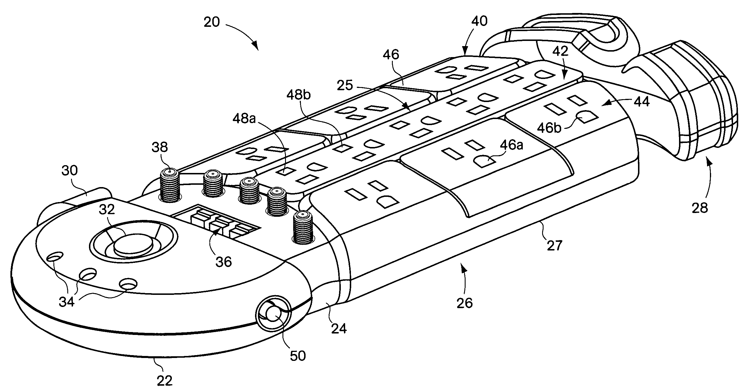
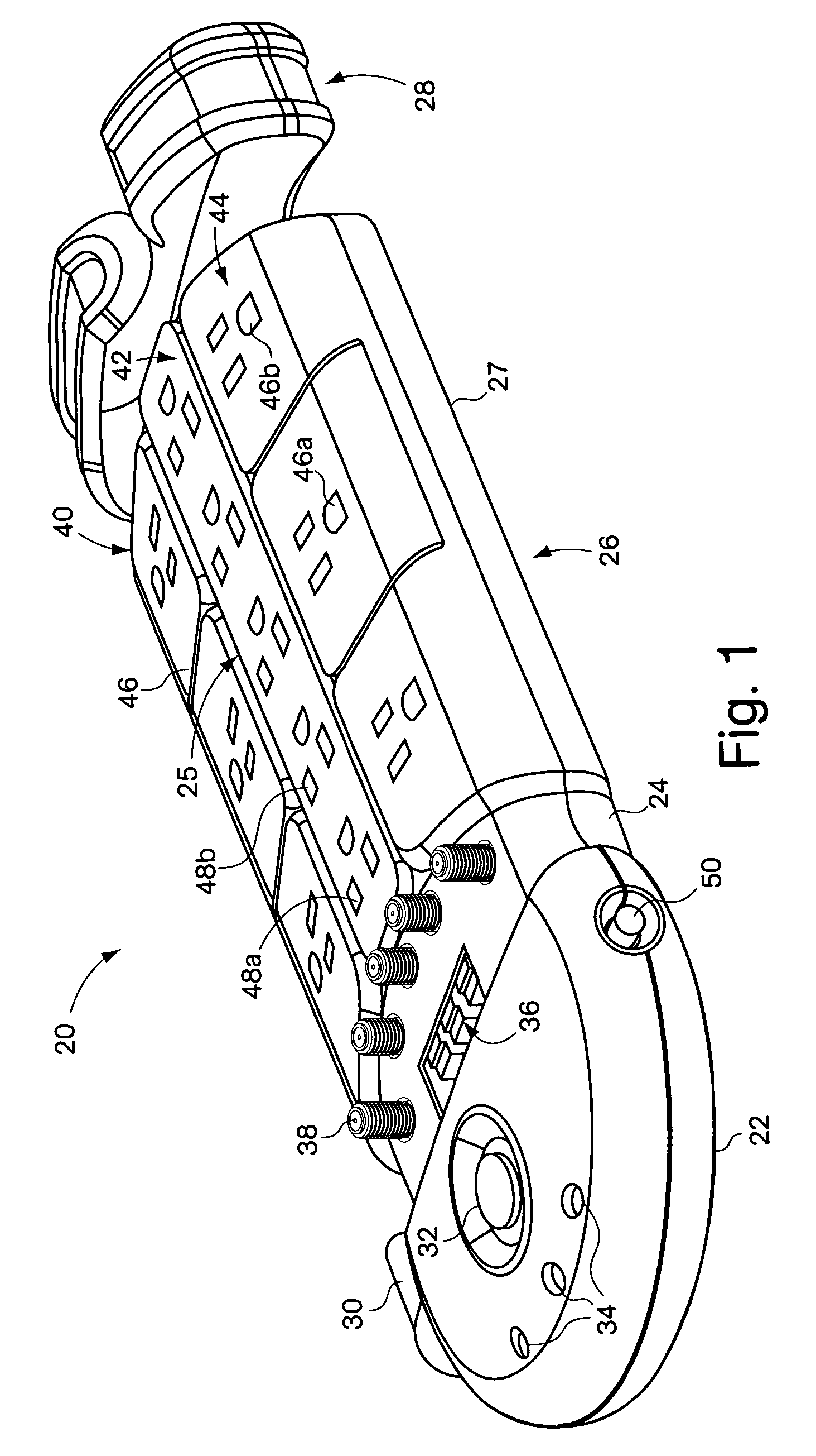
[0009]FIG. 1 is a perspective view of one embodiment of a surge suppressor according to one embodiment of the invention;

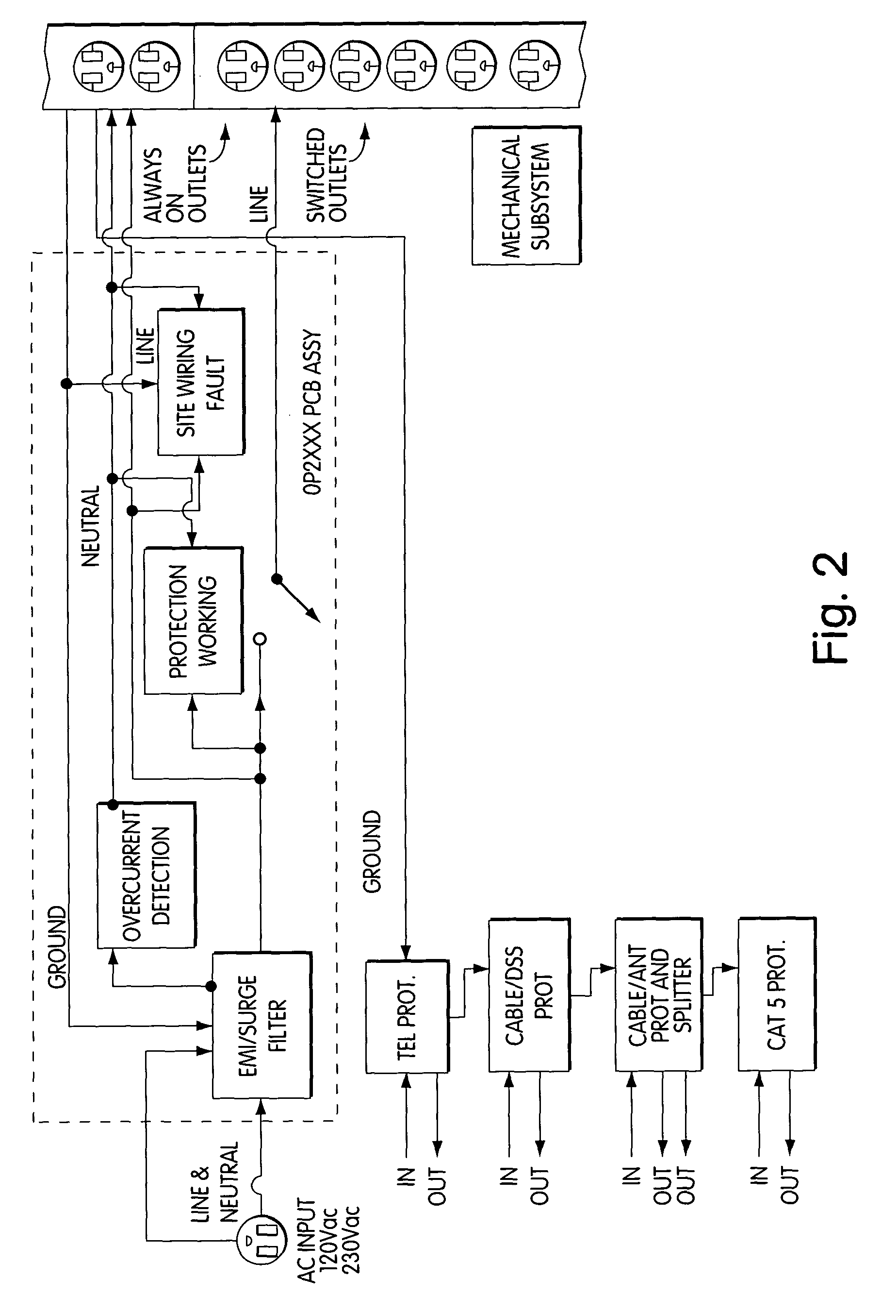
[0010]FIG. 2 is a high-level block diagram of the components of the surge suppressor of FIG. 1;

[0011]FIG. 3A is an exploded bottom perspective view of the surge suppressor of FIG. 1;

[0012]FIG. 3B is an exploded top perspective view of an alternative embodiment of a surge suppressor according to the present invention;

[0013]FIG. 4 is a cutaway view of the MOV and thermal fuse isolation structure;

[0014]FIG. 5 is a perspective view of one embodiment of the intermediate section, e.g., the data section, of the surge suppressor of FIG. 1;

[0015]FIG. 6 is a perspective view of the bottom of the surge suppressor of FIG. 1;

[0016]FIG. 7 is a perspective view of the bottom of the surge suppressor of FIG. 6 with the cord manager pulled out of and away from the surge suppressor housing;

[0017]FIG. 8 is a perspective view of the top of the surge suppressor of FIG. 1 with the power ...


PUM


Abstract

The invention relates to surge suppressors. One embodiment provides a surge suppressing device including: a power circuit having an MOV and a thermal fuse in proximity to the MOV; an isolation structure containing the MOV and the thermal fuse; and a plurality of utility outlets in electrical communication with the power circuit. The isolation structure isolates the MOV and thermal fuse from at least a portion of the surge-suppressing device and encapsulates emissions from the MOV during an overvoltage event. Another embodiment provides a surge suppressing device including: a power section having a power circuit; an intermediate section adjacent to the power section; and an outlet section adjacent to the intermediate section such that the intermediate section separates the power section and the outlet section. The outlet section includes a plurality of utility outlets in electrical communication with the power circuit. Further embodiments are described.

Description

BACKGROUND OF THE INVENTION[0001]The present invention relates to surge suppressors and, more specifically, to a surge suppressor having utility outlets and / or a power cord.[0002]Conventional personal surge suppressors, that is non-industrial surge protectors having utility outlets and a power cord, often include a metal oxide varistor (MOV) as part of a surge suppressing circuit. When an MOV fails, it can expel emissions, e.g., debris, that can result in a cascade of other events / failures. One attempt to prevent such a catastrophic failure of the MOV involves taping the MOV to a thermal fuse that is part of the surge suppressing circuit. Taping the MOV(s) to a thermal fuse is not an ideal solution because heat may be generated on the opposite side of the MOV from the thermal fuse and thus the MOV can still fail. Furthermore, taping the MOV to the thermal fuse is labor intensive.[0003]In addition, when a MOV fails it can disperse carbon onto the board to which it is attached. This p...

Claims


Application Information

Patent Timeline
Patent Type & Authority Patents(United States)
IPC IPC(8): H02H3/00H01R13/70H01R13/713H01R25/00
CPCH01R25/003H01R13/70H01R13/713H01R2201/18H01R2201/04H01R2201/16H01R25/00H02H3/105H02H3/20H02H3/38
Inventor FOURNIER, GREGGERMAGIAN, MARK H.BELL, RONNIE L.
Owner AMERICA POWER CONVERSION CORP
Why Eureka
Try Eureka