Digital automatic level control system

a level control system and digital technology, applied in the direction of gain control, transmission monitoring, pulse technique, etc., can solve the problems of reducing pa efficiency, delay in reaction time of alc, and devices in satellites that cannot work efficiently with such signals, etc., to achieve a large time constant, slow power variation, and zero delay in reaction time

Active Publication Date: 2007-03-20
NORTHROP GRUMMAN SYST CORP
View PDF5 Cites 9 Cited by
  • Summary
  • Abstract
  • Description
  • Claims
  • Application Information

AI Technical Summary

Benefits of technology

[0011]The DALC system is thus advantageous over prior analog based systems because it can effectively estimate signal parameters both in the future and past in order to process a gain constant with which to level the signal parameter. In contrast, prior art systems incorporated analog input and output signals using only power estimates from the past. This forced an ALC to have a large time constant (reaction time) and extra hardware. When considering a bursty signal, whose power changes from zero to some level in virtually no time, and conversely from some power level to zero power in no time, if only the information from the past or future is used to process a gain constant, part of the signal burst may be lost. However, by choosing the maximum of these two power estimates, the subject DALC system can anticipate the beginning of a signal burst, and still have enough delay to compensate the end of a signal burst. Therefore, there is effectively zero delay in reaction time to determine the optimal gain constant. In addition, there is no oscillation of the calculated gain constant in situations where the signal power changes quickly, such as with bursty data. The DALC can thus level signals that have relatively slow power variations (due to rain and other atmospheric conditions) and also signals that have quick power variations (due to bursts of data). In addition, the multiple channel embodiment can perform leveling on a channel-by-channel basis, in addition to performing leveling on groups of sub-channels without requiring extra ALC modules. Another benefit of the DALC system is that it can be realized in the same application specific circuit (ASIC) as other digital devices, such as the channelizer in a satellite receiver application, therefore reducing extra hardware.

Problems solved by technology

One problem with receiving signals that vary in power over a wide range is that devices in the satellites often cannot work efficiently with such signals.
To compensate for this undesirable effect, an engineering trade must be made, considering the maximum and minimum input powers, to set the gain of the PA in order that these nonlinearities are not produced, a process termed “backing off.” If the input power to the PA varies by a great amount, the PA must be backed off by a large value, resulting in reduced PA efficiency.
This is disadvantageous, because classical control theory must be employed, resulting in a delay in reaction time of the ALC, and / or sub-optimal leveling.
As a result, such schemes do not work well with certain types of rapidly varying signals, such as are employed in burst communications schemes, for example.
In addition, analog based schemes cannot be efficiently adapted for use with digital signals such as are employed in the aforementioned digital transponder, for example.

Method used


Image

  • Digital automatic level control system
  • Digital automatic level control system
  • Digital automatic level control system

Examples


first embodiment

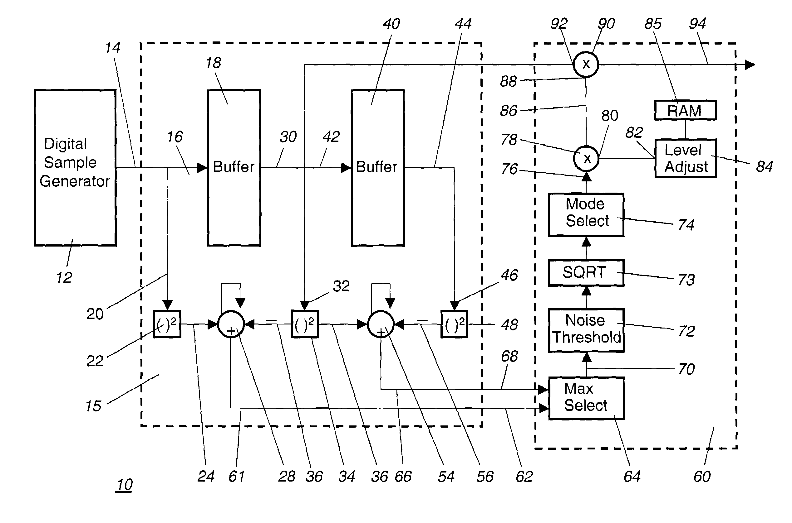
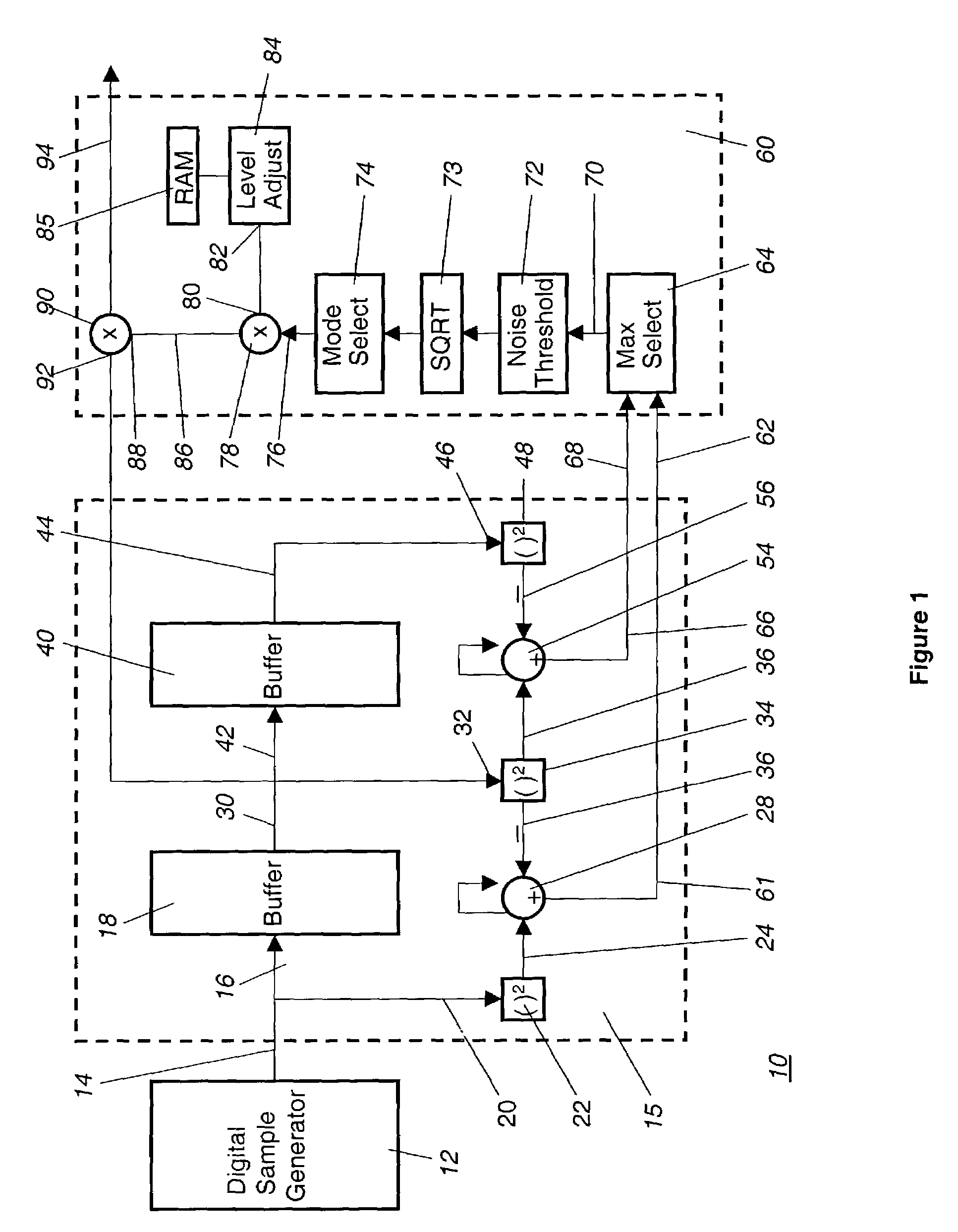
[0016]The basic concepts of the present invention can first be understood on a single channel or single user basis. With reference to FIG. 1, the present invention is illustrated comprising a digital automatic level control (DALC) system 10. The DALC system 10 is designed for controlling the level or amplitude of any single channel signal that is either in the form of, or has been converted into, a sequence of digital time samples. In one preferred application, the DALC system 10 is employed to control the power level of a digital communications signal that is received by a satellite. It will of course be understood that the embodiments of the invention can be employed in any automatic signal level or gain control application.

[0017]In the embodiment illustrated in FIG. 1, an incoming signal is input to a digital sampling generator 12 that generates on an output 14, a sequence of digital time samples of the incoming signal. The digital sampling generator 12 is not an actual element o...

second embodiment

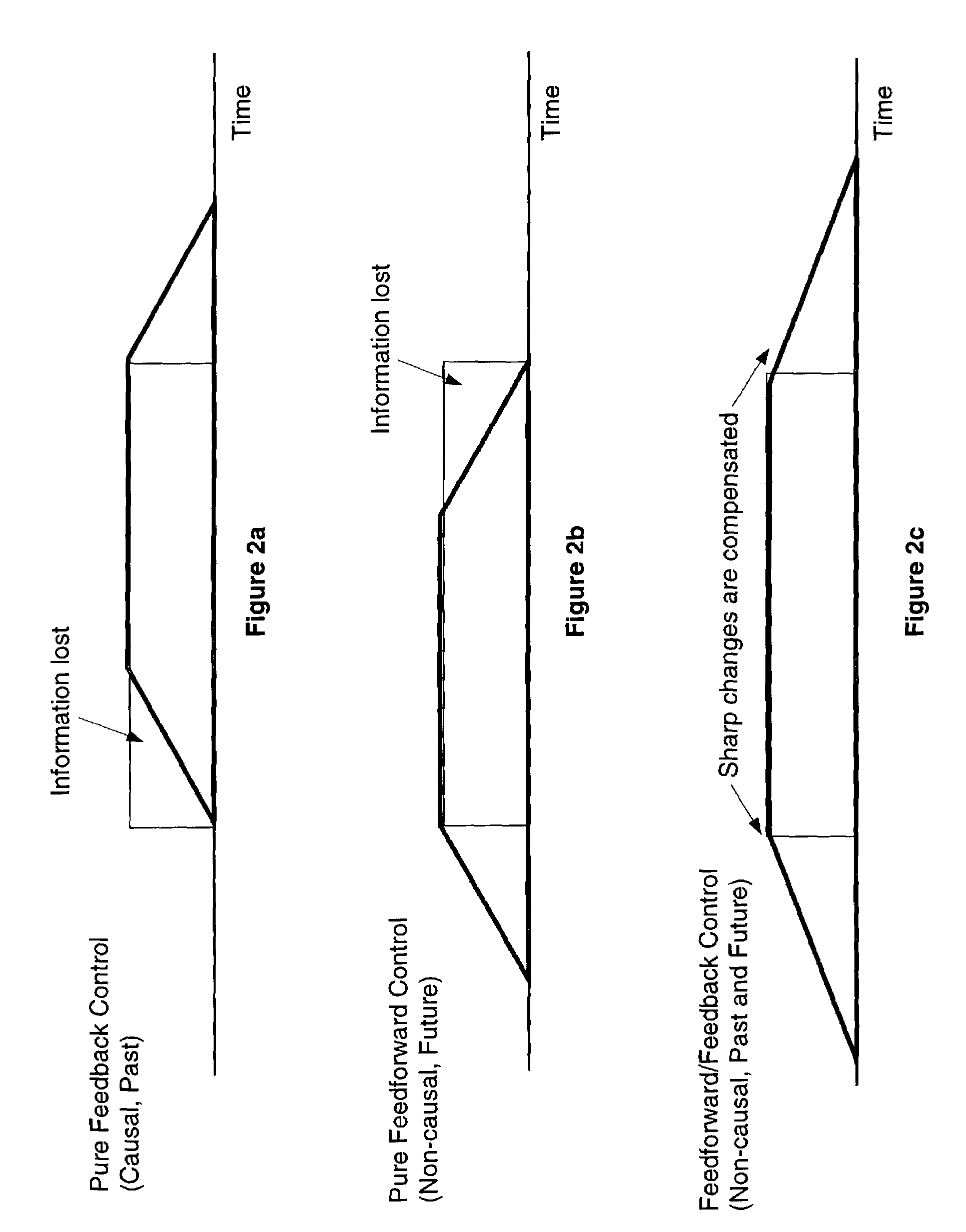
[0032]In conclusion, the present invention provides a digital automatic level control system that is particularly suited for detecting and leveling rapidly varying signals, such as bursty signals. The use of multiple delay elements enables the DALC system to estimate signal parameters both in the future and in the past in order to process a gain constant with which to level the signal parameter. Using the DALC system, leveling can be performed on a channel-by-channel basis, in addition to performing leveling on groups of sub-channels without requiring extra ALC modules.


PUM


Abstract

A digital automatic level control system employs delay elements, which enable information about a signal parameter from the past, present and future to be processed to provide an optimal gain that can be used to level rapidly varying signals, such as bursty signals. As digital time samples of a signal are passed through first and second buffers, first and second accumulators maintain running sums that are related to the sum of the samples presently in the first and second buffers, respectively. The sums in the first and second accumulators represent information about the signal parameter for the future and the past, respectively. By choosing the maximum of these two values, the system can anticipate the beginning of a signal burst, and still have enough delay to compensate the end of a signal burst. In one embodiment of the invention, multiple channel signals can be leveled, either individually or in groups.

Description

BACKGROUND OF THE INVENTION[0001]1. Field of the Invention[0002]The present invention relates in general to a digital automatic level control system that employs digital elements for monitoring and controlling a signal parameter, such as power, voltage, etc. The system can control the levels or gains of multiple signals or channels either individually or in groups. Through use of information relating to the signal parameter's past, present and future levels, the system can respond accurately to quickly varying signals, such as bursty signals.[0003]2. Description of the Background Art[0004]There are numerous applications where power or other parameter levels of signals must be adjusted to facilitate processing. For example, in satellite communications systems, signals transmitted from sources in different areas of a satellite's uplink beam where atmospheric and antenna gain may vary, result in received power at the satellite that varies on a user-by-user basis. In addition, suboptima...

Claims


Application Information

Patent Timeline
Patent Type & Authority Patents(United States)
IPC IPC(8): H04L27/08H03G3/30
CPCH03G3/3089
Inventor DHALLA, CYRUS A.MUNOZ, MICHAEL S.
Owner NORTHROP GRUMMAN SYST CORP
Why Eureka
Try Eureka