

Onboard indicator
a technology of indicator and indicator body, applied in the field of indicators, can solve the problems of misplaced documentation, confusion, failure to identify items for servicing, etc., and achieve the effect of reducing confusion and simple and efficient communication
- Summary
- Abstract
- Description
- Claims
- Application Information
AI Technical Summary
Benefits of technology
Problems solved by technology
Method used
Image

Examples
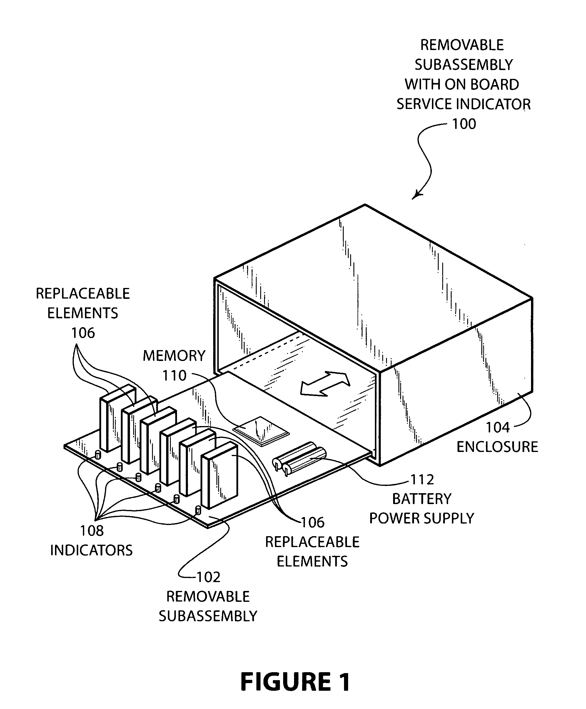
embodiment 100
[0018]FIG. 1 illustrates an embodiment 100 of the present invention showing a removable subassembly with an onboard service indicator. The removable subassembly 102 is normally housed in the enclosure 104 during normal operation. The removable subassembly 102 contains several replaceable elements 106. If one of the elements 106 is to be serviced, the indicators 108 may be illuminated to indicate which of the multiple elements 106 requires servicing. A circuit contained in the subassembly 102 may query the memory 110 using the battery power supply 112.
[0019]The embodiment 100 may contain a subassembly 102 of an electronic system, such as a storage system or other electronic subassembly that contains serviceable elements 106. When the subassembly 102 is removed from the enclosure 104, communication between a host controller and the subassembly is cut off. However, the non-volatile memory 110 may contain information that is useful in the service and repair of the subassembly 102. A cir...
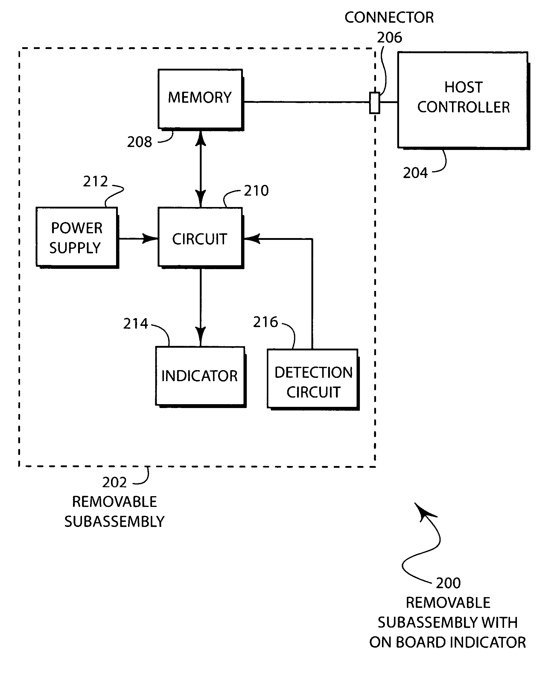
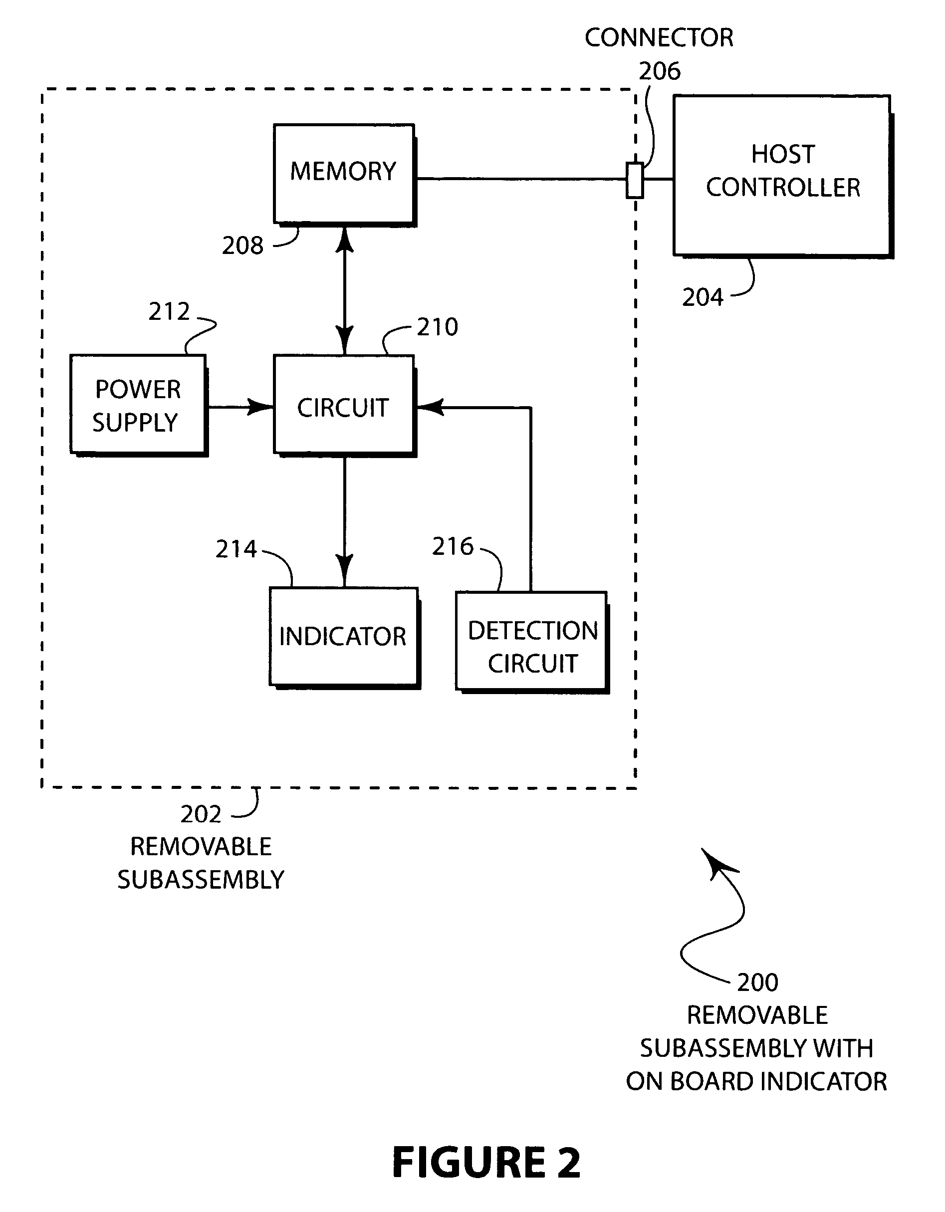
embodiment 200
[0026]FIG. 2 is a block diagram of a removable subassembly shown in FIG. 1 hereof. Embodiment 200 has a removable subassembly having an onboard indicator. The removable subassembly 202 is connected to a host controller 204 through a connector 206. The host controller 204 is connected directly to memory 208. Memory 208 is also connected to the on board circuit 210, which is connected to a power supply 212, an indicator 214, and an optional detection circuit 216.
[0027]The host controller 204 may communicate directly with the memory 208 while the subassembly 202 is in the normal operating state and the connector 206 is engaged. In some embodiments, the removable subassembly may be engaged to the connector 206 through a blind mate connector system. In such a system, the engagement of the removable subassembly into a card cage or enclosure may engage the connector 206, thus enabling the host controller 204 to query, write, and change the memory 208.
[0028]The detection circuit 216 may be ...
embodiment 300
[0029]FIG. 3 is a flow diagram illustration of an embodiment 300 of the method of the present invention showing a method for indicating serviceable elements. The host controller first writes the status to memory in block 302. Next, the subassembly is disconnected from the host controller in block 304. Power is applied to the on board circuit in block 306. The on board memory is queried in block 308 and the status of the replaceable elements is displayed on the indicators in block 310. If the status of the replaceable element has changed in block 312, the memory is updated in block 314. If the status has not changed in block 312, and the subassembly has not been reconnected to the host in block 316, the loop continues with block 312. If the subassembly has been reconnected in block 316, the host controller reads the updated status in block 318 and takes appropriate action in block 320. The process returns to block 302.
[0030]The embodiment 300 illustrates a method by which data may be...
PUM
 Abstract
Description
Claims
Application Information