Systems and methods for storing and handling drill cuttings

a technology of drill cuttings and storage methods, applied in the direction of transportation and packaging, separation processes, borehole/well accessories, etc., to achieve the effect of facilitating the passage of drilling cuttings materials

Active Publication Date: 2007-03-27
VARCO I P INC
View PDF133 Cites 76 Cited by
  • Summary
  • Abstract
  • Description
  • Claims
  • Application Information

AI Technical Summary

Benefits of technology

[0014]The present invention, in certain aspects, discloses a vessel for selectively holding drilling cuttings material, the vessel having: a body, the body having a hollow container with an interior space for receiving drilling cuttings material and from which drilling cuttings material may exit from the body; a first opening through which the drilling cuttings material is introducible into the hollow container; a second opening through which the drilling cuttings material is passable out from the hollow container; movement apparatus, the movement apparatus having a movement member within the hollow container and movable adjacent the second opening to facilitate passage of the drilling cuttings material into the second opening; and an exit opening through the body through which drilling cuttings can exit from the hollow container.

Problems solved by technology

Due to its expense, attempts are made to recover and re-use the used drilling mud.

Method used


Image

  • Systems and methods for storing and handling drill cuttings
  • Systems and methods for storing and handling drill cuttings
  • Systems and methods for storing and handling drill cuttings

Examples


Embodiment Construction

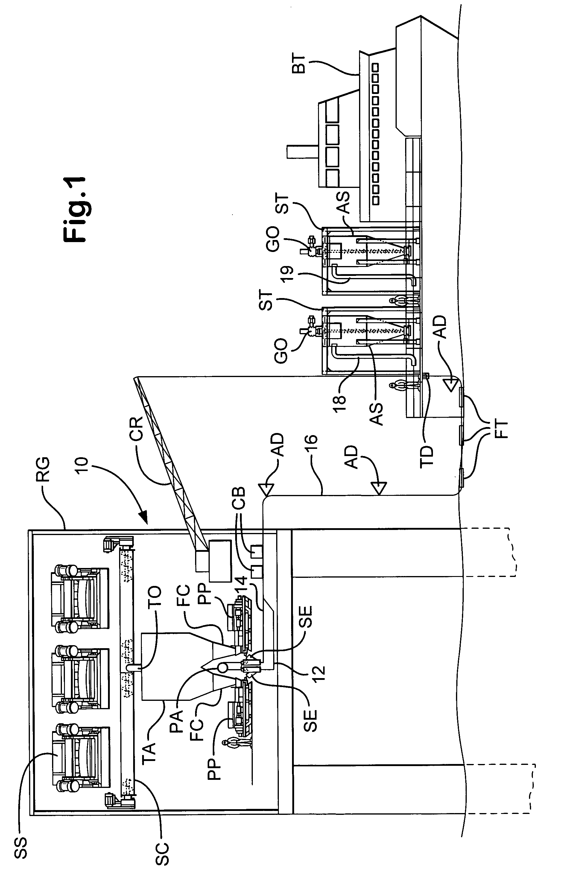
[0066]FIG. 1 shows a system 10 according to the present invention which has one or more (three shown) shale shakers SS mounted on an offshore rig RG. The shale shakers process drilling fluid having drilling solids, drilled cuttings, debris, etc. entrained therein. Separated solids and / or cuttings (with minimal liquid) exit the shale shakers S and are fed to a conveyor SC (or to any other suitable cuttings movement apparatus or device) which moves the separated solids to a feed opening TO of a tank TA.

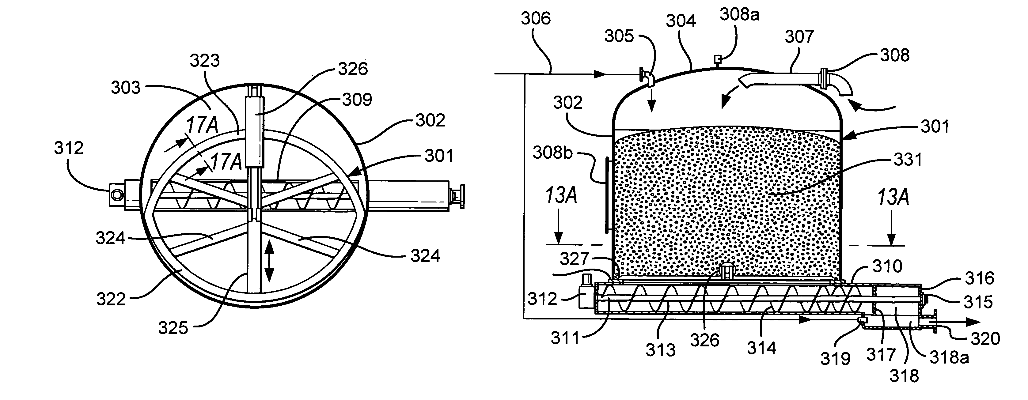
[0067]Solids from the tank TA are pumped, optionally, by one or more pumps PP (two shown) in a line 16 and, optionally, to and through collection devices; e.g. optional cuttings boxes CB are shown in FIG. 1. Pressurized air from a pressurized air source flows to slurry expansion chambers SE in which the density of the solids pumped from the tank TA is reduced. In one particular embodiment air is provided at about 3000 cubic feet per minute to 6000 cubic feet per minute (or about 400 to ...


PUM

PropertyMeasurementUnit
specific gravityaaaaaaaaaa
diameteraaaaaaaaaa
diameteraaaaaaaaaa

Abstract

Vessels for selectively holding drilling cuttings material and methods employing such vessels; the vessels, in at least certain aspects, having a body with a hollow container with an interior space for receiving drilling cuttings material and from which the material may exit from the body; a first opening through which the material enters into the container; a second opening through which the material passes out from the container; and movement apparatus with a movement member within the container movable adjacent the second opening to facilitate passage of the material into the second opening; and in certain aspects, the vessels having moisture-content sensor apparatus on the body for sensing moisture content of material within a vessel; conduit apparatus for conducting drilling cuttings from the exit opening; valve apparatus for selectively controlling flow of material in the conduit apparatus; and a controller in communication with the moisture-content sensor apparatus and the valve apparatus for selectively controlling flow in the conduit apparatus.

Description

RELATED APPLICATION[0001]This is a continuation-in-part of U.S. application Ser. No. 10 / 392,285 filed Mar. 19, 2003 now U.S. Pat. No. 6,936,092, and Ser. No. 10 / 764,825 filed Jan. 26, 2004 now U.S. Pat. No. 6,988,567, which applications are incorporated fully herein for all purposes.BACKGROUND OF THE INVENTION[0002]1. Field of the Invention[0003]The present invention is directed to the movement of drilled cuttings (wet, damp, or dry), to the positive pressure pneumatic transport of such drilled cuttings solids, and, in particular aspects, to the movement of oilfield drilled cuttings or other solids for disposal, onward transportation, storage or further processing.[0004]2. Description of Related Art[0005]The prior art discloses various methods for the positive pressure pneumatic continuous pneumatic transport of low slurry density and low particle density dry solids and non-continuous high slurry density transport of high particle density wet material. Many low density slurries typi...

Claims


Application Information

Patent Timeline
Patent Type & Authority Patents(United States)
IPC IPC(8): E21B21/06E21B41/00
CPCB65G53/10B65G53/12E21B21/066B65G53/66B65G65/44B65G53/60E21B21/06E21B21/065E21B23/06
Inventor BURNETT, GEORGE ALEXANDERCRABB, COLINWOOD, DAVIDSEYFFERT, KENNETH WAYNEHERBEN, WILLIAM CHRISTIANMCINTOSH, JAMES MICHAEL
Owner VARCO I P INC
Why Eureka
Try Eureka