Drill bit

a drill bit and drill bit technology, applied in the field of drill bits, can solve problems such as complex construction

Inactive Publication Date: 2007-03-27
WEATHERFORD TECH HLDG LLC
View PDF111 Cites 17 Cited by
  • Summary
  • Abstract
  • Description
  • Claims
  • Application Information

AI Technical Summary

Benefits of technology

[0020]Preferably, the cutters are rotatable around a non-radial axis. The cutters thus provide a shearing or scooping action as the bit is rotated. The cutter axes are preferably parallel, but may be convergent or divergent. Preferably, each cutter axis lies in a plane which is non-perpendicular to the body axis, although the cutter axes may be perpendicular to the body axis to provide a less aggressive cutting action.
[0021]Preferably, the cutters are mounted on arms pivotally mounted to the body. The cutter axes may lie in a plane which is non-parallel to the bit body lateral axis which is perpendicular to the pivot axis or axes. This facilitates provision of a circular swept cutting area, and the avoidance of an uncut area as the cutters are extended. In other embodiments, particularly when the bit is capable of drilling in both first and second configurations, the cutter axes may lie in a plane which is parallel to the bit body axis; any area left unswept with the cutters in the second configuration will have already been removed by the drilling of a pilot hole with the cutters in the first configuration. The arms may be mounted on a common pivot axis.
[0022]Preferably, the cutters are supported at both ends, and most preferably provided with bearings and seals at both ends, and are thus likely to be more robust than a conventional roller cone bit, in which the cutters are supported at only one end.

Problems solved by technology

Also, although numerous expandable bits have been proposed, these are of complex construction and the applicant is unaware of any such bit in current commercial usage.

Method used


Image

  • Drill bit
  • Drill bit
  • Drill bit

Examples


Embodiment Construction

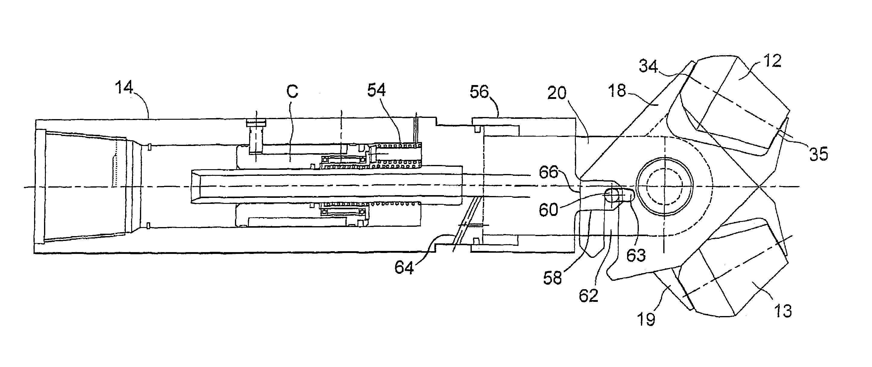
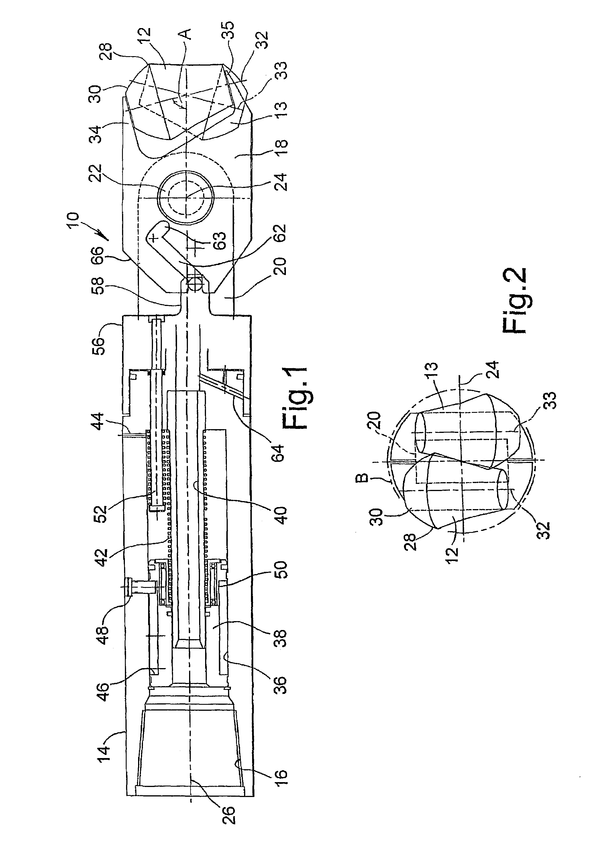
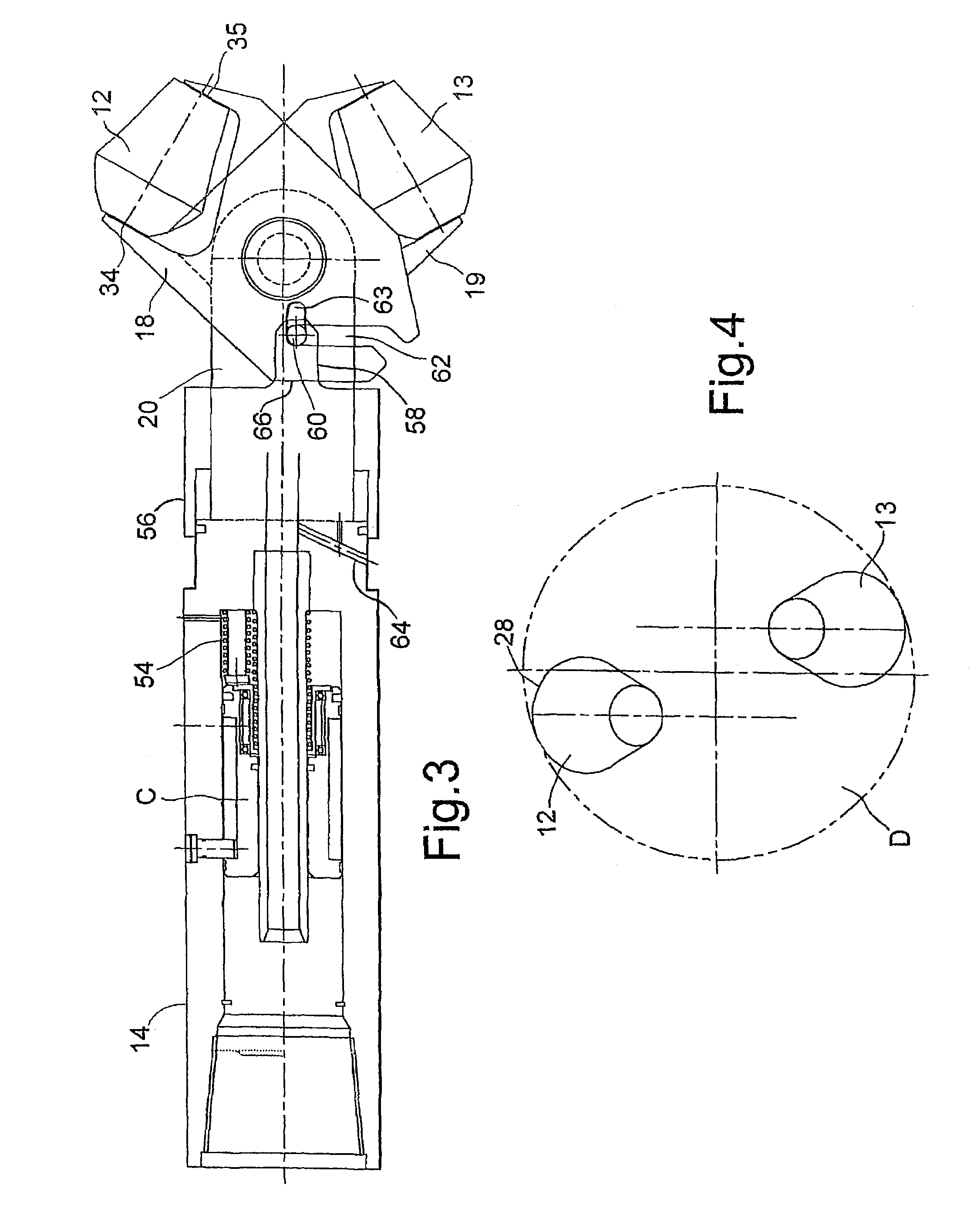
[0037]The reference is first made to FIG. 1 of the drawings, which illustrates a drill bit 10 in accordance with a preferred embodiment of the present invention. As will be described, the bit 10 comprises conical roller cutters 12, 13 which are movable between a smaller diameter first configuration, as shown in FIGS. 1 and 2, and a larger diameter second configuration, as shown in FIGS. 3 and 4. This allows the bit 10 to pass through bore restrictions and then be extended to cut larger diameter bores, as will be described.

[0038]The bit 10 comprises a generally cylindrical body 14 adapted for mounting on the end of a drill string. As illustrated, the body 14 is provided with a box-type connector 16 for engaging a pin-type connector on the end of a drill string. The cutters 12 are mounted on the lower end of the body 14 by respective pivoting arms 18, 19. The lower end of the body 14 is in the form of an extension 20 which provides mounting for a pivot pin 22 on which the arms 18, 19 ...


PUM


Abstract

An expandable drill bit comprises a body for mounting on a support string and two roller cutters mounted on the body. The cutters are movable between a smaller diameter first configuration and a larger diameter second configuration. In one embodiment the bit is adapted to drill with the cutters in both the first and second configurations.

Description

CROSS-REFERENCE TO RELATED APPLICATIONS[0001]This application claims benefit of PCT patent application number PCT / GB01 / 02858 filed Jun. 27, 2001. PCT application number PCT / GB01 / 02858 claims benefit of Great Britain patent application number 0015714.9 filed Jun. 28, 2000.BACKGROUND OF THE INVENTION[0002]1. Field of the Invention[0003]This invention relates to drill bits. Aspects of the invention relate to both fixed and expandable drill bits.[0004]2. Description of the Related Art[0005]Deep bores, for example, as utilized to access subsurface hydrocarbon-bearing formations, are conventionally drilled using drill bits mounted on the end of a string of drill pipe, the drill pipe being rotated from surface. It is also known to drill bores using drill bits driven by downhole motors, and to mount drill bits on relatively flexible coil tubing. There are currently two main drill bit forms in common usage, that is roller cone bits and fixed cutter bits, the former cutting primarily by a cru...

Claims


Application Information

Patent Timeline
Patent Type & Authority Patents(United States)
IPC IPC(8): E21B7/28E21B10/34
CPCE21B10/345
Inventor PIA, GIANCARLO T.
Owner WEATHERFORD TECH HLDG LLC
Why Eureka
Try Eureka