[0005]The object of the present invention is therefore to provide a bearing shell for a ball-and-socket joint that possesses good mechanical and tribological material properties along with low material costs. Providing a process for manufacturing the bearing shell according to the present invention is likewise an object of the present invention.
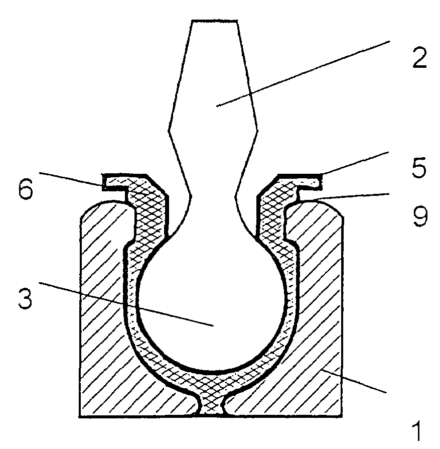
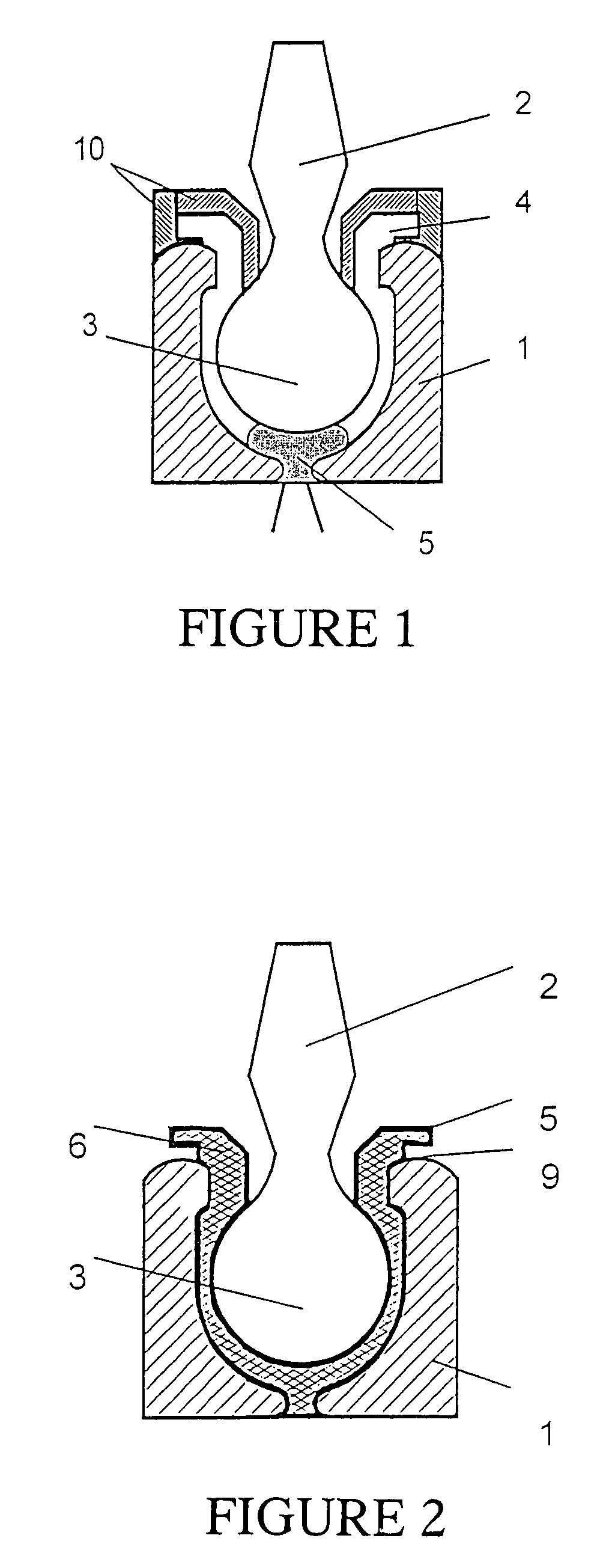
[0007]The bearing shell according to the present invention has two components: A jacket component, which determines the tribological properties (properties that pertain to friction and wear) of the bearing shell, and a
core component within the jacket component, which determines the mechanical properties, e.g., the
creep properties, strength,
toughness, etc., of the bearing shell. The jacket surface is advantageously designed to be such that it forms a high-quality tribological outer friction layer for a joint ball and also forms the ball-and-socket joint housing at the same time. The interior of the jacket component is advantageously filled with a less expensive
core component. The cost of the material is thus reduced and the service life of the ball-and-socket joint is prolonged at the same time because of the lower friction at the outer friction layer, without having to accept any loss of the mechanical properties of the material. Due to an additional
coating of the ball pivot with fluorinated plastics, sliding lacquers and / or other tribologically suitable
layers, which is performed separately in a preceding operation, the tribological properties of the bearing shell can be increased further, and the service life can be prolonged even more.
[0008]An outwardly directed circular collar, which forms a circular groove together with the ball-and-socket joint housing, may be advantageously made integrally in one piece with the bearing shell in the upper area. The
assembly of the sealing
bellows can thus be substantially simplified, because it may be performed as a result at any point in time.
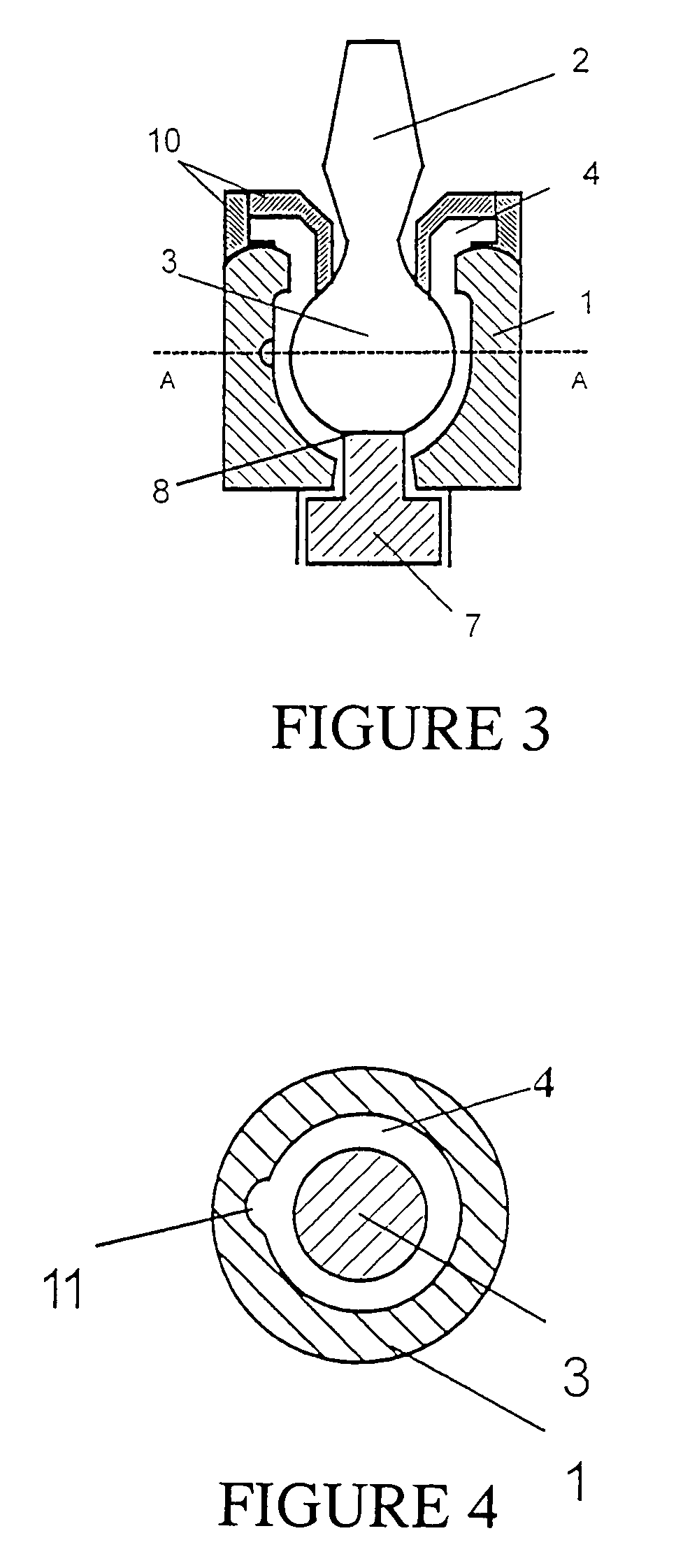
[0009]The process for manufacturing the bearing shell according to the present invention starts with the
insertion of the joint ball into the ball-and-socket joint housing. Together with an at least two-part mold attached, the joint ball and the joint housing form a cavity, into which a first plastic is injected at first such that the cavity will be partially filled. A second plastic is then injected into this first plastic such that the cavity will be completely filled. Due to this co-injection process (sandwich injection molding) and as a consequence of the rheological properties of the two plastics (swelling flow), the first plastic flows over the inserts of the cavity such that it forms the jacket component of the bearing shell, and the second plastic is the core component. A bearing shell with a core and with a jacket surrounding a core, with good tribological and mechanical properties, is thus formed after the cooling. Additional
assembly steps are, in principle, unnecessary. The assembly effort is very low in the process according to the present invention, as a result of which short process times will be obtained.
[0010]The less expensive core component is used, among other things, to completely fill the cavity, and the jacket component is pressed against the walls of the cavity. The shrinkage of the plastic during the
injection molding process is reduced by additives, for example,
fiber reinforcement, and the change in volume brought about by cooling is reduced. In addition, the reinforced core component may be provided with a
blowing agent in order to thus achieve uniform shrinkage without sink marks, bubbles or warping.
[0011]In order to additionally compensate the
volume contraction of the plastics during cooling, it may be advantageous to heat by a heater and cool the ball pivot and / or the housing before and / or during the injection and / or for a time after the injection. The handling is simplified for the use of fiber reinforcements by the fact that the warping is reduced or prevented from occurring.
